Digital i/o, Pull-up/down jumper – Measurement Computing USB-CTR04 User Manual
Page 15
USB-CTR04 User's Guide
Functional Details
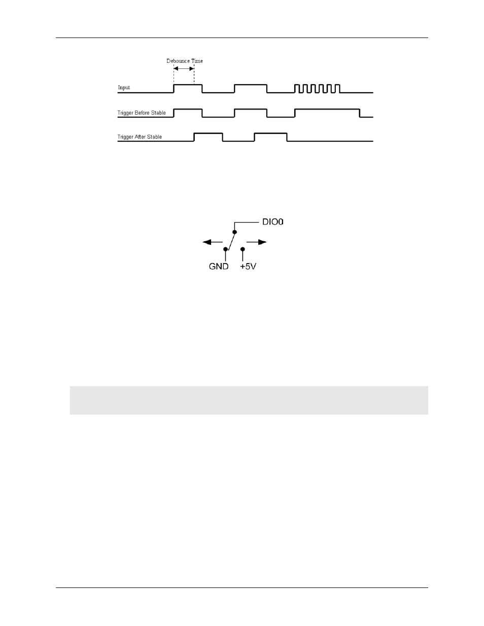
Figure 10. Optimal debounce time for trigger after stable mode
Digital I/O
You can connect up to eight digital I/O lines to
DIO0
through
DIO7
. The digital I/O terminals can detect the
state of any TTL-level input. Refer to the schematic shown in Figure 11.
Figure 11. Schematic showing switch detection by digital channel DIO0
If you set the switch to the +5 V input, DIO0 reads TRUE (1). If you move the switch to GND, DIO0 reads
FALSE
(0).
Pull-up/down jumper
The digital port has 47 kΩ resistors that you can configure as pull-up or pull-down with internal jumper (see
Figure 12 on page 16 for the location of this jumper).
Unconnected inputs are pulled low by default to 0 V through 47 kΩ resistors. The pull-up/pull-down voltage is
common to all 47 kΩ resistors.
You must remove the cover from the device in order to access the jumper.
Caution! The discharge of static electricity can damage some electronic components. Before removing the
device from its housing, either ground yourself using a wrist strap or touch the computer chassis or
other grounded object to eliminate any stored static charge.
To open the case and set the pull-up/down jumper, complete the following steps:
1. Turn the device over and rest the top of the housing on a flat, stable surface.
2. Peel off the four rubber feet on the bottom of the device to access the screws.
3. Remove the four screws from the bottom of the device.
4. Hold both the top and bottom sections together, turn the device over and rest it on the surface, and then
carefully remove the top section of the case to expose the circuit board.
5. Configure the jumper for either pull-up or pull-down. The jumper is configured by default for pull-down
(see Figure 12 and Figure 13).
Figure 12 shows the location of the pull-up/down jumper on the USB-CTR04 with the enclosure removed.
15