Timer output, Ee figure 12, Figure 13) – Measurement Computing USB-CTR04 User Manual
Page 16: Figure 12
USB-CTR04 User's Guide
Functional Details
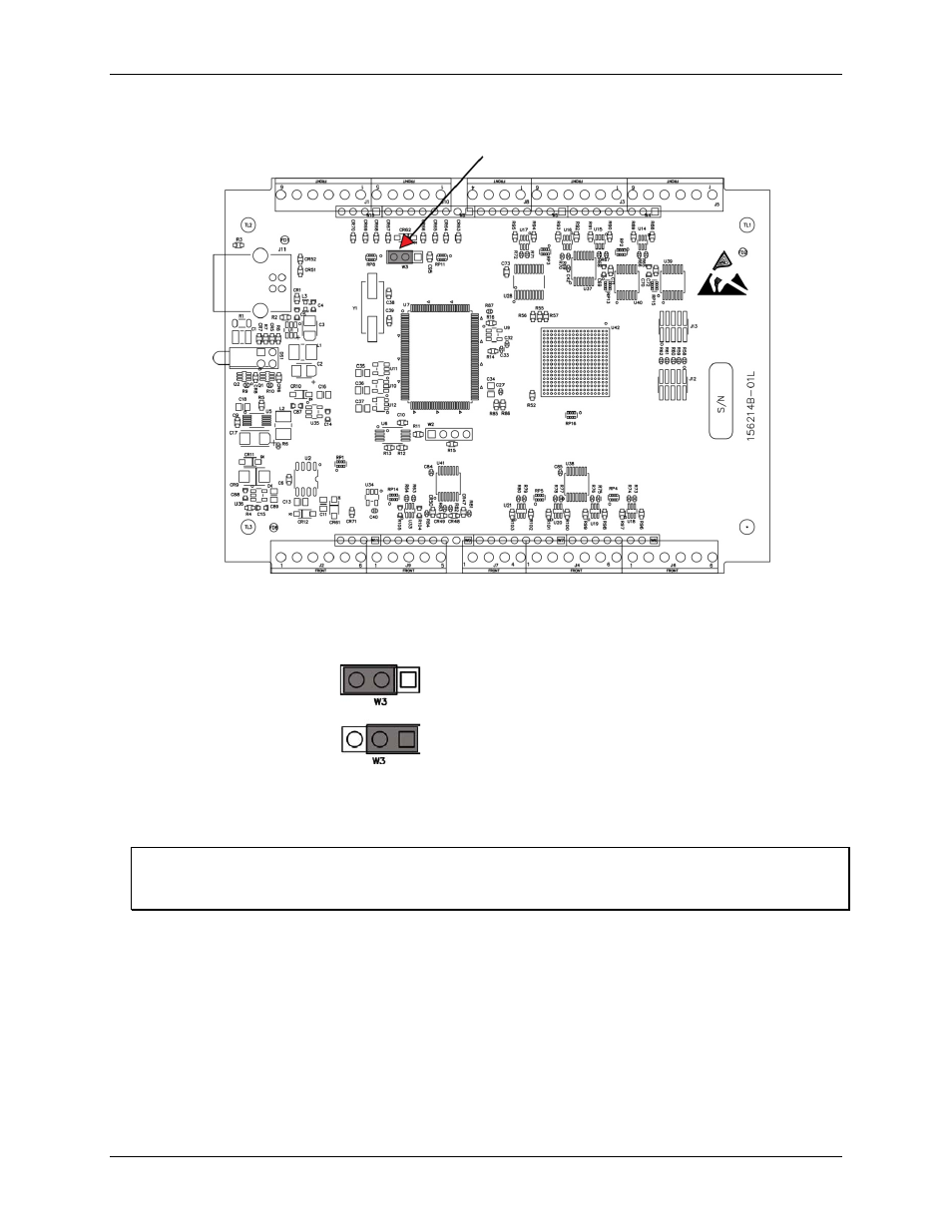
Pull-up/pull-down jumper
Figure 12. Pull-up/down jumper location
The pull-up/down jumper is configured by default for pull-down (see Figure 13).
Pull-down (factory default)
Pull-up
Figure 13. Pull-up/down jumper configurations
To pull the digital inputs high (5 V), configure the jumper for pull-up.
Proper LED alignment
When placing the circuit board within the housing, align the board LEDs with the top of the housing before
attaching the housing bottom.
Timer output
You can use
TMR0
through
TMR3
as 32-bit timer outputs. Each timer can generate a programmable width pulse
with a software-selectable frequency in the range of 0.022 Hz to 48 MHz. At higher frequencies, the timer
output frequency and duty cycle depend on the load impedance and the supply.
The timer output rate and pulse width can be updated asynchronously at any time, however, doing so results in a
pulse stream that is not seamless.
The following timer output options are software-selectable:
pulse frequency
duty cycle (pulse width divided by the pulse period)
16