External trigger, External clock input/output – Measurement Computing USB-CTR04 User Manual
Page 21
USB-CTR04 User's Guide
Specifications
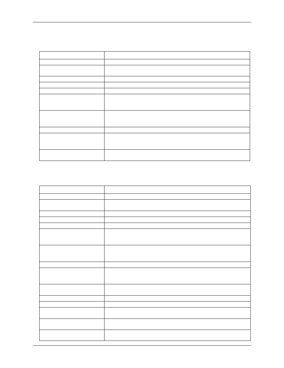
External trigger
Table 4. Digital trigger specifications
Parameter
Specification
Trigger source
External digital; TRIG terminal
Trigger mode
Software-selectable for edge or level sensitive, rising or falling edge, high or low
level.
Trigger latency
100 ns max
Trigger pulse width
100 ns min
Input type
Schmitt trigger, 47 kΩ pull-down to ground with 33 Ω in series
Schmitt trigger hysteresis
0.76 V typ
0.4 V min
1.2 V max
Input high voltage threshold
1.74 V typ
1.3 V min
2.2 V max
Input high voltage limit
5.5 V absolute max
Input low voltage threshold
0.98 V typ
0.6 V min
1.5 V max
Input low voltage limit
–0.5 V absolute min
0 V recommended min
External clock input/output
Table 5. External clock input/output specifications
Parameter
Specification
Terminal names
CLKI, CLKO
Terminal type
CLKI: Input, active on rising edge
CLKO: Output, power on default is 0V, active on rising edge
Input clock frequency
4 MHz, max
Input clock pulse width
10.417 ns min
Input type
Schmitt trigger, 47 kΩ pull-down to ground with 33 Ω in series
Input Schmitt trigger hysteresis
0.76 V typ
0.4 V min
1.2 V max
Input high voltage threshold
1.74 V typ
1.3 V min
2.2 V max
Input high voltage limit
5.5 V absolute max
Input low voltage threshold
0.98 V typ
0.6 V min
1.5 V max
Input low voltage limit
–0.5 V absolute min
0 V recommended min
Output clock frequency
4 MHz, max
Output clock pulse width
10.417 ns
Output high voltage
4.4 V min (IOH = –50 µA)
3.78V min (IOH = –24 mA)
Output low voltage
0.1 V max (IOL = 50 µA)
0.44 V max (IOL = 24 mA)
Output current
24 mA max per pin, constrained to 240 mA across all output pins (counter outputs,
timer outputs, digital outputs, pacer clock output, and +VO)
21