Signal connector, Screw terminal pinout – Measurement Computing USB-CTR04 User Manual
Page 23
USB-CTR04 User's Guide
Specifications
Signal connector
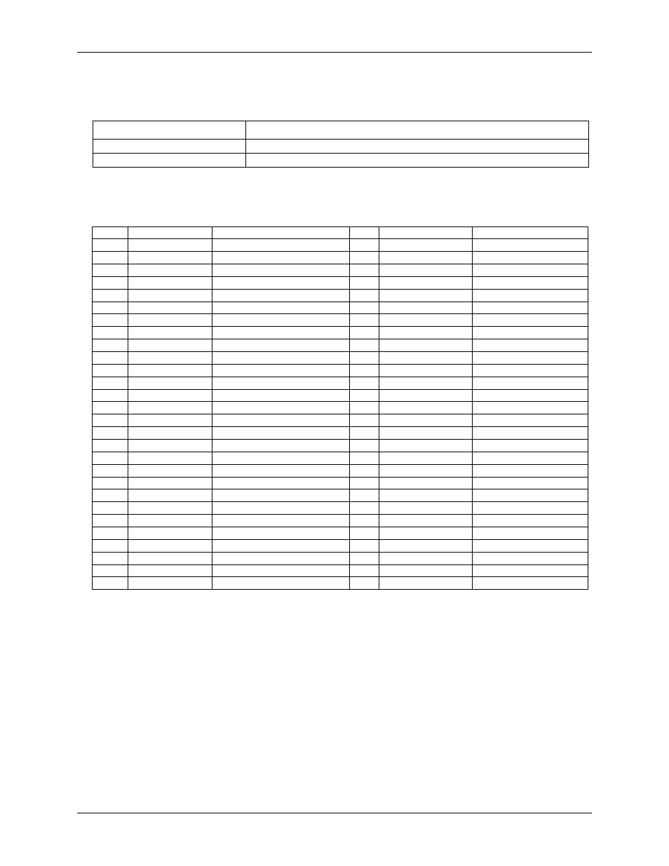
Table 11. Screw terminal specifications
Parameter
Specification
Connector type
Screw terminal
Wire gauge range
16 AWG to 30 AWG
Screw terminal pinout
Table 12. Screw terminal pinout
Pin
Signal name
Pin description
Pin
Signal name
Pin description
1
C0IN
Counter 0 input
28
N/C
No connection
2
C0GT
Counter 0 gate
29
N/C
No connection
3
GND
Digital ground
30
GND
Digital ground
4
C0O
Counter 0 output
31
N/C
No connection
5
C1IN
Counter 1 input
32
N/C
No connection
6
C1GT
Counter 1 gate
33
N/C
No connection
7
GND
Digital ground
34
GND
Digital ground
8
C1O
Counter 1 output
35
N/C
No connection
9
C2IN
Counter 2 input
36
N/C
No connection
10
C2GT
Counter 2 gate
37
N/C
No connection
11
GND
Digital ground
38
GND
Digital ground
12
C2O
Counter 2 output
39
N/C
No connection
13
C3IN
Counter 3 input
40
N/C
No connection
14
C3GT
Counter 3 gate
41
N/C
No connection
15
GND
Digital ground
42
GND
Digital ground
16
C3O
Counter 3 output
43
N/C
No connection
Empty
Empty
17
DIO0
DIO bit 0
44
TMR0
Timer 0 output
18
DIO1
DIO bit 1
45
TMR1
Timer 1 output
19
DIO2
DIO bit 2
46
GND
Digital ground
20
DIO3
DIO bit 3
47
TMR2
Timer 2 output
21
GND
Digital ground
48
TMR3
Timer 3 output
22
GND
Digital ground
49
TRIG
Trigger input
23
DIO4
DIO bit 4
50
GND
Digital ground
24
DIO5
DIO bit 5
51
CLKI
External clock input
25
DIO6
DIO bit 6
52
GND
Digital ground
26
DIO7
DIO bit 7
53
CLKO
Internal clock output
27
GND
Digital ground
54
+VO
User voltage output
23