Pulse width measurement mode, Timing mode – Measurement Computing USB-CTR04 User Manual
Page 11
USB-CTR04 User's Guide
Functional Details
Pulse width measurement mode
You can use the USB-CTR04 to measure the time from the rising edge to the falling edge, or vice versa, on a
counter input signal (CxIN). The measurement is either pulse width low or pulse width high, depending upon
the edge detection setting.
If the counter read period is faster than the input period, pulse widths repeat in the acquisition. The bigger
the difference between the counter read period and the input period, the more pulse widths are repeated.
If the counter read period is slower than the input period, then the acquisition misses some pulse widths.
The bigger the difference between the counter read period and the input period, the more pulse width
values are missed.
Decrease the counter read period in order to increase the number of different pulse widths received.
Every time the pulse width measurement is latched from the counter, the counter is immediately cleared and
enabled to count the time for the next pulse width. The pulse width measurements are latched as they become
available.
The data returned is interpreted as time measured in ticks. This data represents the number of tick size intervals
counted during the pulse width measurement.
Optionally, you can use the counter gate signal (
CxGT
) to gate the counter.
When
CxGT
is high, the counter is enabled.
When
CxGT
is low, the counter is disabled, but holds the count value.
The 96 MHz system clock is used as the timing source. Pulse widths from sub-microsecond to many seconds
can be measured.
Pulse width measurement mode tick size options are software-selectable. The tick size is a fundamental unit of
time derived from the period of the 96 MHz system clock.
Four counter channel tick sizes (pulse width resolutions) are available – 20.83 ns, 208.3 ns, 2083.3 ns, and
20833.3 ns.
Timing mode
You can use the USB-CTR04 to measure the time between an event on
CxIN
and a subsequent event on
CxGT
,
such as the rising or falling edge of one event with respect to the rising or falling edge of another event (based
on the edge detection setting).
Whenever the time measurement is latched from the counter, the counter is immediately cleared and enabled for
accepting the subsequent time period, which starts with the next edge on the main channel.
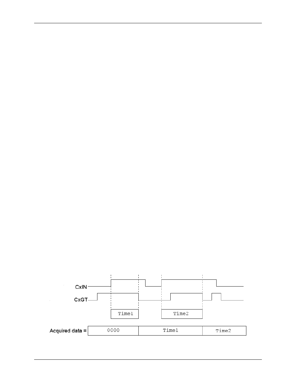
The following example measures the time between the rising edge on a counter input (
CxIN
) and the falling
edge on the counter gate (
CxGT)
. The counter read operation returns zeroes until one complete time
measurement has been taken. Then, the value (time in ticks) is latched by the device until the next time
measurement is completed. At that time, rising edges on the counter input channel clear the counter and falling
edges on the gate input latch the output of the counter.
Figure 4. Counter input channel in timing mode
11