Trigger input, External clock pacing, Power – Measurement Computing USB-CTR04 User Manual
Page 17: Ground
USB-CTR04 User's Guide
Functional Details
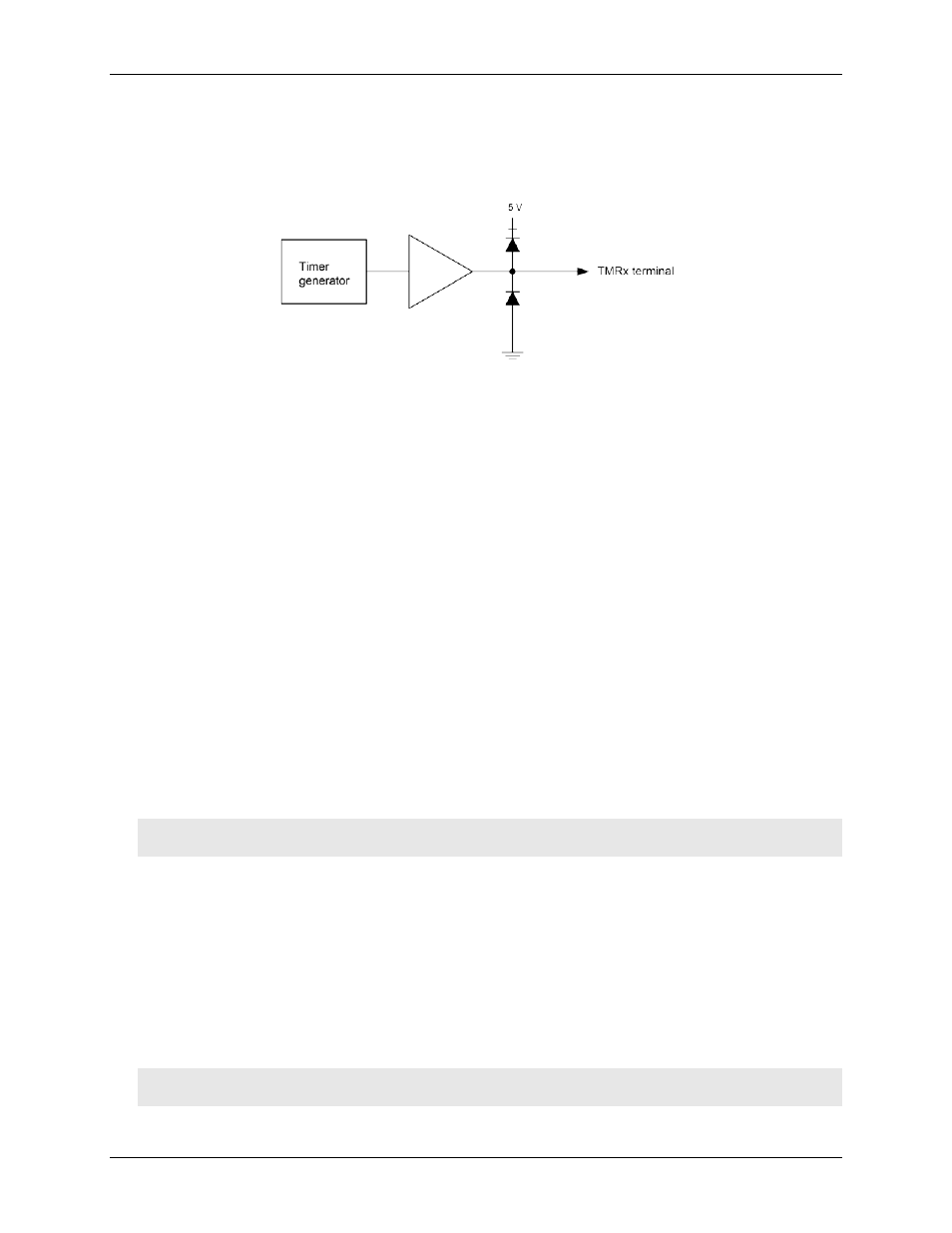
number of pulses to generate
time delay before starting the timer output after it's enabled
resting state of the output (idle high or idle low)
Both the period and time delay ranges are 20.83 ns to 44.739 seconds.
Figure 14. USB-CTR04 PWM timer channel
Trigger input
You can trigger synchronous acquisitions of counter data internally with software or externally using the
TRIG
digital trigger input screw terminal.
The
TRIG
input allows TTL-level triggering with latencies guaranteed to be less than 20.83 ns. The acquisition
can be triggered
on a rising or falling edge, or on a high or low level. The trigger input is TTL logic . Latency is
one sample period, maximum. The input signal range is –0.5 V to 5.5 V maximum. The logic level (1 or 0) and
the rising or falling edge for the discrete trigger input are software-selectable.
When using the external trigger, the counter begins counting when the scan starts, even though acquisition of
the count is held off by the trigger. To coordinate the start of acquisition with the start of the count, you could
use the trigger signal to also trigger the gate of the counter in use. Clearing the counter before starting the scan
will re-arm the gate trigger.
External clock pacing
You can pace synchronous acquisition of counter data by the onboard clock or by an external clock connected
to the
CLKI
external clock input terminal.
Power
You can use the
+VO
power output terminal to supply power to external devices or circuitry.
Caution! The
+VO
terminal is an output. Do not connect to an external power supply or you may damage
the USB-CTR04 and possibly the computer.
The maximum total output current that can be drawn from all USB-CTR04 connections (counter outputs, timer
outputs, digital outputs, pacer clock output, and
+VO
) is 240 mA. This maximum applies to most personal
computers and self-powered USB hubs. Bus-powered hubs and notebook computers may limit the maximum
available output current to 100 mA.
If the current requirement of the device exceeds the current available from the computer, connect to a self-
powered hub or power the computer with an external power adapter.
Ground
The ground (
GND
) connections provide a common ground for the digital, counter, and power connections.
Caution! Make sure that the signals are connected such that there is no potential between PC ground and
signal ground.
17