External clock input/output, Counter, Memory – Measurement Computing USB-7202 User Manual
Page 21
USB-7202 User's Guide
Specifications
21
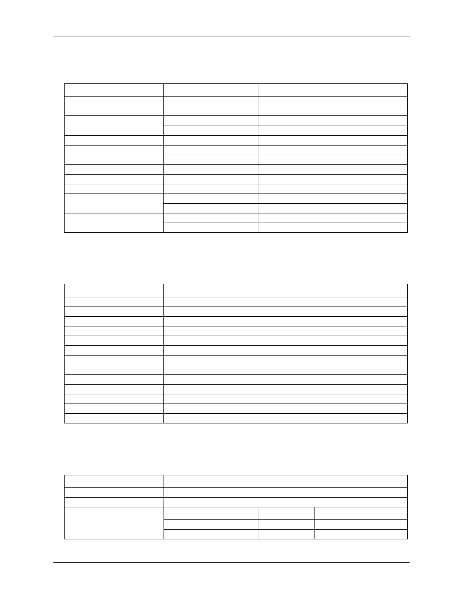
External clock input/output
Table 7. External clock I/O specifications
Parameter
Conditions
Specification
Pin name
SYNC
Pin type
Bidirectional
Software-selectable direction
Output
Outputs internal A/D pacer clock.
Input
Receives A/D pacer clock from external source.
Input clock rate
50 kHz, max
Clock pulse width
Input
1µs min
Output
5µs min
Input leakage current
±1.0µA
Input high voltage
4.0 V min, 5.5 V absolute max
Input low voltage
1.0 V max, –0.5 V absolute min
Output high voltage (Note 3)
IOH = –2.5 mA
3.3 V min
No load
3.8 V min
Output low voltage (Note 3)
IOL = 2.5 mA
1.1 V max
No load
0.6 V max
Note 3:
SYNC is a Schmitt trigger input and is over-current protected with a 1.5
kΩ series resistor.
Counter
Table 8. Counter specifications
Parameter
Specification
Pin name (Note 4)
CTR
Counter type
Event counter
Number of channels
1
Input type
TTL, rising edge triggered
Input source
CTR screw terminal
Resolution
32 bits
Schmidt trigger hysteresis
20 mV to 100 mV
Input leakage current
±1µA
Input frequency
1 MHz max
High pulse width
500 ns min
Low pulse width
500 ns min
Input high voltage
4.0 V min, 5.5 V absolute max
Input low voltage
1.0 V max, –0.5 V absolute min
Note 4:
CTR is a Schmitt trigger input protected with a 1.5
kΩ series resistor.
Memory
Table 9. Memory specifications
Parameter
Specification
Data FIFO
32,768 samples, 65,536 bytes
EEPROM
1,024 bytes
EEPROM configuration
Address range
Access
Description
0x000-0x1FF
Reserved
512 bytes system and Cal data
0x200-0x3FF
Read/write
512 bytes user area