Digital input/output, External trigger – Measurement Computing USB-7202 User Manual
Page 20
USB-7202 User's Guide
Specifications
20
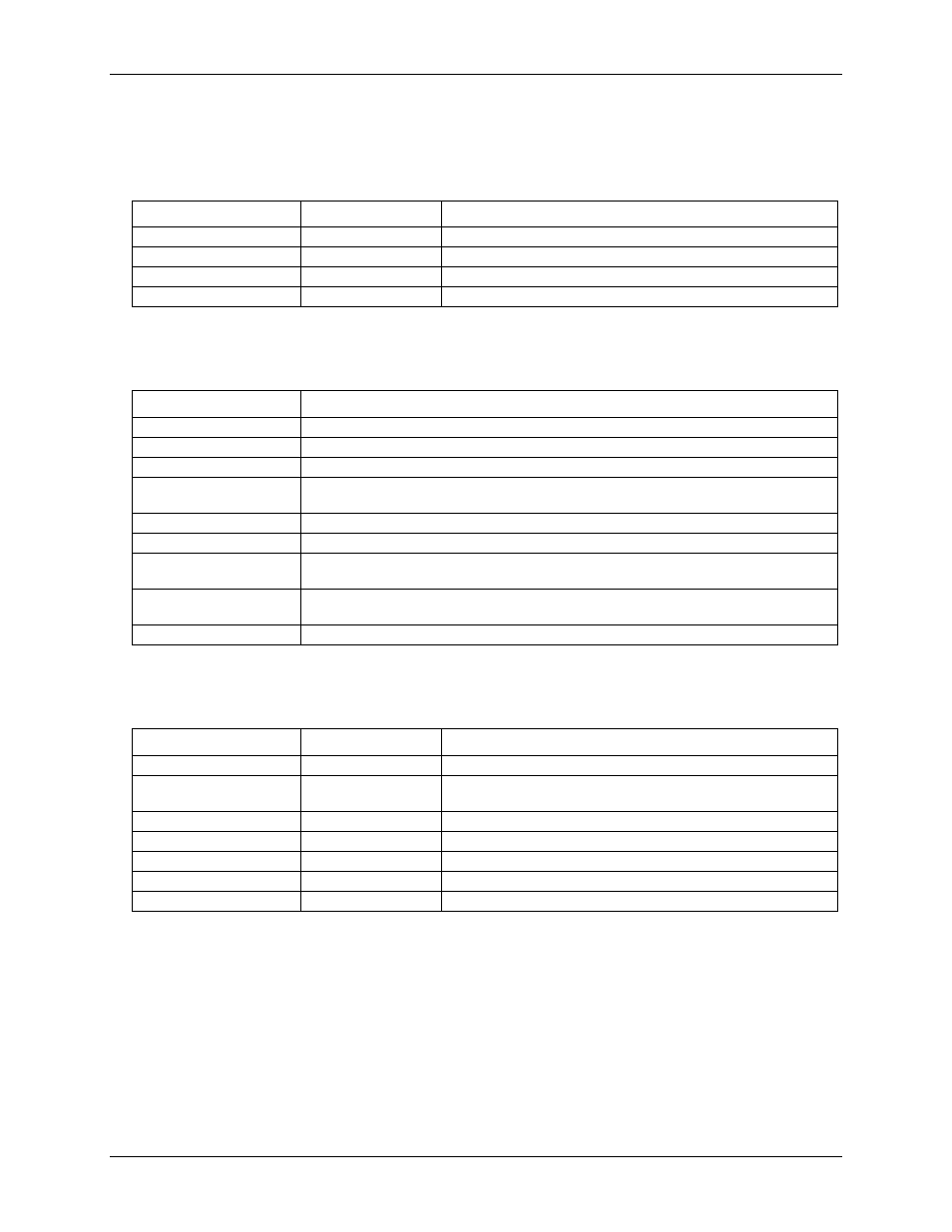
Table 4 summarizes the noise performance for the USB-7202. Noise distribution is determined by gathering
50 K samples with inputs tied to ground at the user connector. Samples are gathered at the maximum specified
sampling rate of 50 kS/s.
Table 4. Noise performance
Range
Typical counts
LSBrms
±10 V
10
1.52
±5 V
10
1.52
±2 V
11
1.67
±1 V
14
2.12
Digital input/output
Table 5. Digital I/O specifications
Parameter
Specification
Digital type
CMOS
Number of I/O
8 (DIO0 through DIO7)
Configuration
Independently configured for input or output
Pull-up/pull-down
configuration
All pins configurable via jumper (JP1) to Vs or ground via 47
kΩ resistors.
Input high voltage
2.0 V min, 5.5 V absolute max
Input low voltage
0.8 V max, –0.5 V absolute min
Output high voltage
(IOH = –2.5 mA)
3.8 V min
Output low voltage
(IOL = 2.5 mA)
0.7 V max
Power on and reset state
Input
External trigger
Table 6. External trigger specifications
Parameter
Conditions
Specification
Trigger source (Note 2)
External digital
TRIG_IN
Trigger mode
Software-selectable
Edge sensitive: user configurable for CMOS compatible rising or
falling edge.
Trigger latency
10 µs max
Trigger pulse width
1µs min
Input high voltage
4.0 V min, 5.5 V absolute max
Input low voltage
1.0 V max, –0.5 V absolute min
Input leakage current
±1.0µA
Note 2:
TRIG_IN is a Schmitt trigger input protected with a 1.5K Ohm series resistor.