Accuracy – Measurement Computing USB-7202 User Manual
Page 15
USB-7202 User's Guide
Functional Details
15
Accuracy
The overall accuracy of any instrument is limited by the error components within the system. Quite often,
resolution is incorrectly used to quantify the performance of a measurement product. While "16-bits" or "1
part in 65,536" does indicate what can be resolved, it provides little insight into the quality, or accuracy, of an
absolute measurement. Accuracy specifications describe the actual measurement that can be relied upon with
a USB-7202.
There are three types of errors which affect the accuracy of a measurement system:
offset
gain
nonlinearity
The primary error sources in the USB-7202 are offset and gain. Nonlinearity is small in the USB-7202, and is
not significant as an error source with respect to offset and gain.
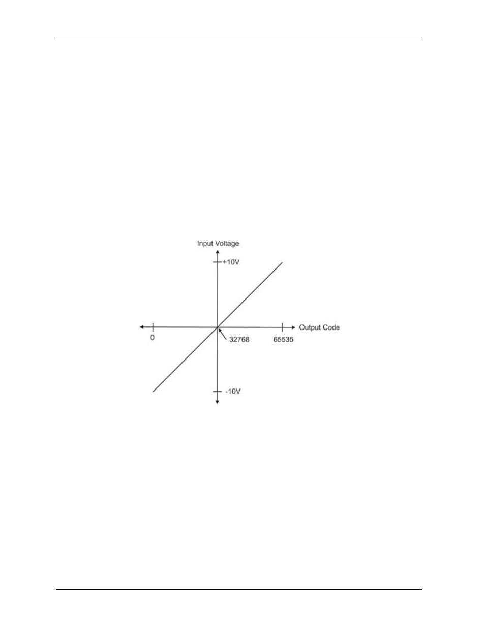
Figure 6 shows an ideal, error-free, USB-7202 transfer function. The typical calibrated accuracy of the USB-
7202 is range-dependent, as explained in the Specifications chapter on page 19. We use a ±10 V range as an
example of what you can expect when performing a measurement in this range.
The accuracy plots in Figure 6 are drawn for clarity and are not drawn to scale.
Figure 6. Ideal ADC transfer function
The USB-7202 offset error is measured at mid-scale. Ideally, a zero volt input should produce an output code
of 32,768. Any deviation from this is an offset error. Figure 7 shows the USB-7202 transfer function with an
offset error. The typical offset error specification for the USB-7202 on the ±10 V range is ±1.66 mV. Offset
error affects all codes equally by shifting the entire transfer function up or down along the input voltage axis.