Trigger/sync connector, Sync jumper (p6), Trigger jumper (p7) – Measurement Computing USB-7202 User Manual
Page 12: Led indicators
USB-7202 User's Guide
Functional Details
12
Modifications are required in order to use the OEM connector
We recommend that you return the device to the factory for this modification.
Should you have the capabilities to perform the modifications, the following change is required: in order to
create a USB connection via the OEM connector, locations R30and R36 must be populated. We recommend
that you populate with 0603 size 0
Ω resistors or provide solder bridges to close the gaps.
Trigger/Sync connector
The Trigger/Sync connector provides two signals — SYNC and TRIG_IN. These signals are also available
on the screw terminal (refer to
on page 14 for details about these signals).
Trigger/Sync connector pinout
Pin Signal Name
Pin Signal Name
1
TRIG_IN
2
GND
3
N/C
4
GND
5
SYNC
6
GND
7
N/C
8
GND
9
N/C
10
N/CD
Use a 0.1" box header when making connections to the Trigger/Sync connector.
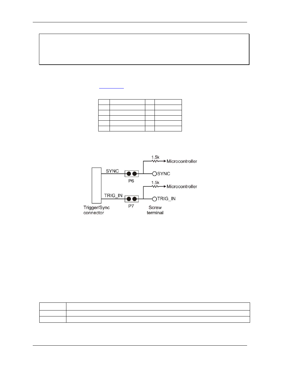
The Trigger/Sync connector internally connects its SYNC and TRIG_IN pins to the screw terminal via
jumpers
P6
and
P7
.
Figure 3. Jumper P6 and P7 schematic
Sync jumper (P6)
The Sync jumper internally connects the SYNC pin on the Trigger/Sync connector to the SYNC pin on the
screw terminal. Remove this jumper on boards that will not send/receive the SYNC signal through the
SYNC/TRIG connector. Refer to Figure 2 on page 11 for the location of this jumper.
Trigger jumper (P7)
The Trigger jumper internally connects the TRIG_IN pin on the Trigger/Sync connector to the TRIG_IN pin
on the screw terminal. Remove this jumper on boards that will not send/receive the TRIG signal through the
SYNC/TRIG connector. Refer to Figure 2 on page 11 for the location of this jumper.
LED indicators
The USB-7202 has LEDs for power and communication status. See Figure 2 on page 11 for the location of
each LED.
LED type
Indication
Power
Steady green: The device microcontroller is connected to a computer or external USB hub.
Status
Blinking green: data is being transferred over the USB bus.