Screw terminals, Signal connections, Analog input – Measurement Computing USB-7202 User Manual
Page 13: Digital i/o, Pull-up/down configuration
USB-7202 User's Guide
Functional Details
13
Screw terminals
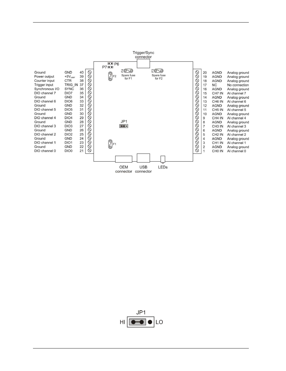
Screw terminal connections in shown in Figure 4.
Figure 4. Screw terminal pinout
Use 16 AWG to 30 AWG when making screw terminal connections.
Signal connections
Analog input
You can connect up to eight analog input connections to screw terminals
CH0 IN
through
CH7 IN
. Connect
unused analog input terminals to ground terminals during operation. All AI channels are configured for
single-ended input mode. The input voltage ranges are ±10 V, ±5 V, ±2.0 V, ±1.0 V.
Each analog signal is referenced to signal ground (AGND), and requires two wires:
The wire carrying the signal to be measured connects to CH# IN.
The second wire connects to AGND.
Digital I/O
You can connect up to eight digital I/O lines to screw terminals
DIO0
to
DIO7
. Each digital bit is configurable
as either input or output. When configured for input, the digital I/O terminals can be used to detect the state of
any TTL-level input.
Pull-up/down configuration
The digital pins are configurable via jumper
JP1
for pull-up to USB +5 V (HI) or pull-down to ground (LO).
On power up and reset the DIO pins are driven high.
Figure 5. Jumper JP1 configuration