Power consumption, Connector and pin out, Auxiliary connector p3 pinout – Measurement Computing PCI-DAS4020/12 User Manual
Page 26
PCI-DAS4020/12 User's Guide
Specifications
26
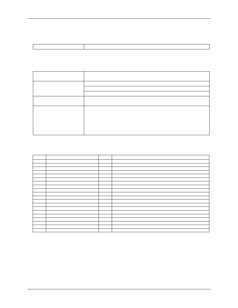
Power consumption
Table 13. Power consumption specifications
+5 V Operating (A/D to FIFO)
1.5 A typical, 2.0 A max
Connector and pin out
Table 14. Connector specifications
Connector type
BNC connector: five standard female connectors
Auxiliary connector (P3): 40-pin header connector
Compatible cables (for the
40-pin auxiliary connector)
C40FF-x
C40-37F-x
BP40-37-x
Compatible accessory products
with the C40FF-x cable
CIO-MINI40
Compatible accessory products
with the C40-37F-x cable
or
with the BP40-37-x and the
C37FF-x or C37FFS-x cable
CIO-MINI37
SCB-37
CIO-ERB24
CIO-ERB08
SSR-RACK24
SSR-RACK08
Auxiliary connector P3 pinout
Table 15. Auxiliary connector (P3) pin out
Pin
Signal Name
Pin
Signal Name
1
INTERRUPT IN *
2
+5V
3
INTERRUPT ENABLE *
4
GND
5
FIRSTPORTB Bit 7
6
FIRSTPORTC Bit 7 (A/D Pacer Gate)
7
FIRSTPORTB Bit 6
8
FIRSTPORTC Bit 6 (A/D Stop Trigger In)
9
FIRSTPORTB Bit 5
10
FIRSTPORTC Bit 5 (Start Trigger In/Ext Clock)
11
FIRSTPORTB Bit 4
12
FIRSTPORTC Bit 4
13
FIRSTPORTB Bit 3
14
FIRSTPORTC Bit 3
15
FIRSTPORTB Bit 2
16
FIRSTPORTC Bit 2
17
FIRSTPORTB Bit 1
18
FIRSTPORTC Bit 1
19
FIRSTPORTB Bit 0
20
FIRSTPORTC Bit 0
21
GND
22
FIRSTPORTA Bit 7
23
n/c
24
FIRSTPORTA Bit 6
25
GND
26
FIRSTPORTA Bit 5
27
n/c
28
FIRSTPORTA Bit 4
29
GND
30
FIRSTPORTA Bit 3
31
n/c
32
FIRSTPORTA Bit 2
33
GND
34
FIRSTPORTA Bit 1
35
+5V
36
FIRSTPORTA Bit 0
37
GND
38
D/A GND
39
D/A OUT 0
40
D/A OUT 1
* Pins 1 and 3 have 10 K pull-up resistors installed.