Connecting the board for i/o operations, Connectors, cables – i/o connectors, Bnc connectors – Measurement Computing PCI-DAS4020/12 User Manual
Page 11
PCI-DAS4020/12 User's Guide
Installing the PCI-DAS4020/12
11
Connecting the board for I/O operations
Connectors, cables
– I/O connectors
The table below lists the board connectors, applicable cables, and compatible accessory products for the PCI-
DAS4020/12.
Board connectors, cables, compatible hardware
Connector type
BNC connector: five standard female connectors
Auxiliary connector (P3): 40-pin header connector
Compatible cables (for the
40-pin auxiliary connector)
C40FF-x
C40-37F-x
BP40-37-x
Compatible accessory products
with the C40FF-x cable
CIO-MINI40
Compatible accessory products
with the C40-37F-x cable
or
with the BP40-37-x and the C37FF-x or
C37FFS-x cable
CIO-MINI37
SCB-37
CIO-ERB24
CIO-ERB08
SSR-RACK24
SSR-RACK08
Information on signal connections
General information regarding signal connection and configuration is available in the Guide to Signal
Connections. This document is available on our web sit
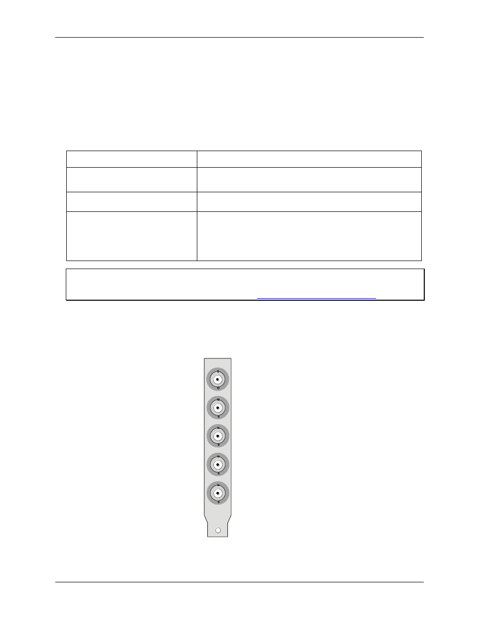
BNC connectors
The board’s analog input and trigger input connectors are standard female BNC connectors that are visible from
the rear of the computer when you install the board.
Channel 0
Channel 1
Channel 2
Channel 3
TRIG /Ext Clk
Figure 1. Analog inputs and trigger input BNC connectors