Pin out – auxiliary connector, Cabling – Measurement Computing PCI-DAS4020/12 User Manual
Page 12
PCI-DAS4020/12 User's Guide
Installing the PCI-DAS4020/12
12
Pin out
– auxiliary connector
The pin out for the board’s 40-pin on-board auxiliary connector (labeled
P3
on the board) is listed below. Pin 1
is identified by a beveled edge on the board silkscreen.
40-pin auxiliary connector P3
Signal Name
Pin
Pin
Signal Name
D/A OUT 1
40
39
D/A OUT 0
D/A GND
38
37
GND
FIRSTPORTA Bit 0
36
35
+5V
FIRSTPORTA Bit 1
34
33
GND
FIRSTPORTA Bit 2
32
31
n/c
FIRSTPORTA Bit 3
30
29
GND
FIRSTPORTA Bit 4
28
27
n/c
FIRSTPORTA Bit 5
26
25
GND
FIRSTPORTA Bit 6
24
23
n/c
FIRSTPORTA Bit 7
22
21
GND
FIRSTPORTC Bit 0
20
19
FIRSTPORTB Bit 0
FIRSTPORTC Bit 1
18
17
FIRSTPORTB Bit 1
FIRSTPORTC Bit 2
16
15
FIRSTPORTB Bit 2
FIRSTPORTC Bit 3
14
13
FIRSTPORTB Bit 3
FIRSTPORTC Bit 4
12
11
FIRSTPORTB Bit 4
FIRSTPORTC Bit 5 (Start Trigger In/Ext Clock)
10
9
FIRSTPORTB Bit 5
FIRSTPORTC Bit 6 (A/D Stop Trigger In)
8
7
FIRSTPORTB Bit 6
FIRSTPORTC Bit 7 (A/D Pacer Gate)
6
5
FIRSTPORTB Bit 7
GND
4
3
INTERRUPT ENABLE *
+5V
2
1
INTERRUPT IN *
PCI slot
↓
* Pin 1 and pin 3 have 10 K pull-up resistors installed.
Use pin 38 for analog output return
When using the analog output pins D/A OUT 0 (pin 39) and D/A OUT 1 (pin 40), use D/A GND only (pin 38)
for the return.
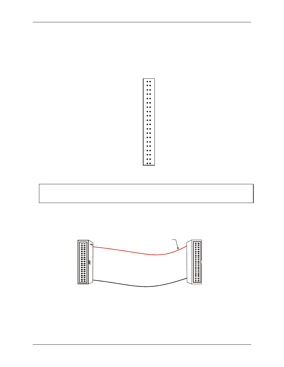
Cabling
For signal connections and termination, you can use the CIO-MINI40 screw terminal board and C40FF-x cable.
For connections to 37-pin screw terminal boards, you can use the C40-37F-x cable.
The red stripe
identifies pin # 1
40-pin Female
IDC Connector
1
2
39
40
40-pin Female
IDC Connector
1
2
39
40
Figure 2. C40FF-x cable