Field wiring, signal termination and conditioning, Digital signal conditioning, Field wiring, signal – Measurement Computing PCI-DAS4020/12 User Manual
Page 16: Termination and conditioning
PCI-DAS4020/12 User's Guide
Installing the PCI-DAS4020/12
16
20
1
37
19
20
1
37
19
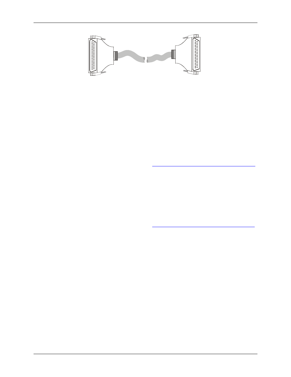
Figure 7. C37FFS-x cable
Field wiring, signal termination and conditioning
You can use the following MCC screw terminal board to terminate field signals and route them into the PCI-
DAS4020/12 board using the C40FF-x cable:
CIO-MINI40 – 40-pin universal screw terminal board.
You can use the following MCC screw terminal boards to terminate field signals and route them into the PCI-
DAS4020/12 board using the C40-37F-x cable directly or by combining the BP40-37-x cable with the C37FF-x
or C37FFS-x cable:
CIO-MINI37 – 37-pin universal screw terminal board.
SCB-37 – 37 conductor, shielded signal connection/screw terminal box.
Details on these products are available on our web sit
Digital Signal Conditioning
For digital signal conditioning, you can connect the PCI-DAS4020/12 to the following boards using the C40-
37F-x cable directly or by combining the BP40-37-x cable with the C37FF-x or C37FFS-x cable.
CIO-ERB24 – 24 Form C, 6A relays.
CIO-ERB08 – Eight Form C, 6A relays.
SSR-RACK24 – 24-channel solid state module rack.
SSR-RACK08 – 24-channel solid state module rack.
Details on these products are available on our web sit