1 introduction, 2 installation – Measurement Computing PC104-AC5 User Manual
Page 5
1 INTRODUCTION
The PC104-AC5 is a 24-line digital I/O board. The control register which sets the
direction of the I/O ports is identical to an 8255 in mode 0 (see 8255 data sheet). The
I/O pins are high-drive TTL compatible.
The connector is a 50-pin header which is compatible with the pin-out of OPTO-22
and GORDOS solid state relay racks. If you are using an OPTO or GORDOS form
factor solid state relay rack, the PC104-AC5 can be connected directly to the relay
rack through a 50-pin cable such as the C50FE-2.
A group of application notes is included to assist in electrical interfacing.
2 INSTALLATION
Before you open your computer and install the board, install and run InstaCal, the
installation, calibration and test utility included with your board. InstaCal will guide
you through switch and jumper settings for your board. Detailed information
regarding these settings can be found below. Refer to the Extended Software
Installation manual for InstaCal installation instructions.
The PC104-AC5 has one bank of base address-select switches, an interrupt select
jumper, a wait state select jumper and a jumper for configuring the function of pin 49
which must be set before
installing the board in your
computer.
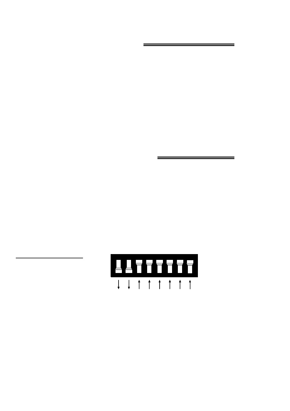
2.1 BASE ADDRESS
On the base address switches,
(Figure 2-1), each switch
position corresponds to one of
the PC bus address lines. By
placing the switch down, the
address decode logic responds to
that address bit.
Figure 2-1. Base Address Switch - 300h Shown
1
2
A2 04
9 8 7 6 5 4 3 2
Sw Hex
A9 200
A8 100
A7 80
A6 40
A5 20
A4 10
A3 8
A2 4