Measurement Computing PC104-AC5 User Manual
Page 19
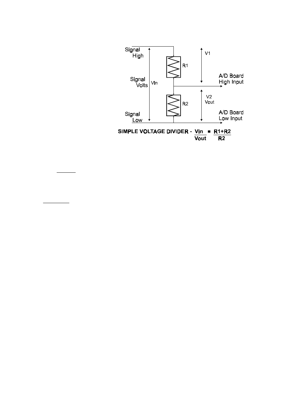
In a voltage divider, the voltage
across one of the resistors in a
circuit is proportional to that
resistance divided into the total
resistance in the circuit.
The object is to choose two
resistors with the proper ratio
relative to the full scale of the
digital input and the maximum
signal voltage.
For dropping the voltage
proportionally (attenuation) the
formula for is:
For a given attentuation, pick a handy resistor and call it
R2, then use this formula to calculate R1.
R1=(A-1)*R2
For example, if the signal varies between 0 and 20 volts
and you wish to measure that with an analog input with a
full scale range of 0 to 10 volts, the Attenuation is 2:1 or
just 2.
2 = 10K+10K
10K
The variable Attenuation is the proportional difference
between the signal voltage max and the full scale of the
analog input.
Attenuation = R1+R2
R2
Digital inputs also may require voltage dividers. For example, if you wish to input a
24 volt digital signal, you cannot connect that directly to the PC104-AC5 digital
inputs. The voltage must be dropped to 5 volts max. The Attenuation is 24:5 or 4.8.
Use the equation above to find an appropriate R1 if R2 is 1K. Remember that a TTL
input is 'on' when the input voltage is greater than 2.5 volts.
IMPORTANT NOTE
The resistors, R1 and R2, are going to dissipate all the power in the
divider circuit according to the equation Current = Voltage /
Resistance and power = current-squared times resistance. The
higher the value of the resistance (R1 + R2) the less power
dissipated by the divider circuit. Here is a simple rule:
15