3 register architecture, 1 introduction – Measurement Computing PC104-AC5 User Manual
Page 10
3 REGISTER ARCHITECTURE
3.1 INTRODUCTION
The PC104-AC5 contains three data and one control register for the 24 lines of digital
I/O.
The first address, or BASE ADDRESS, is determined by setting a bank of switches on
the board.
Register manipulation is best left to experienced programmers as most of the
PC104-AC5 functions are implemented in the easy to use Universal Library.
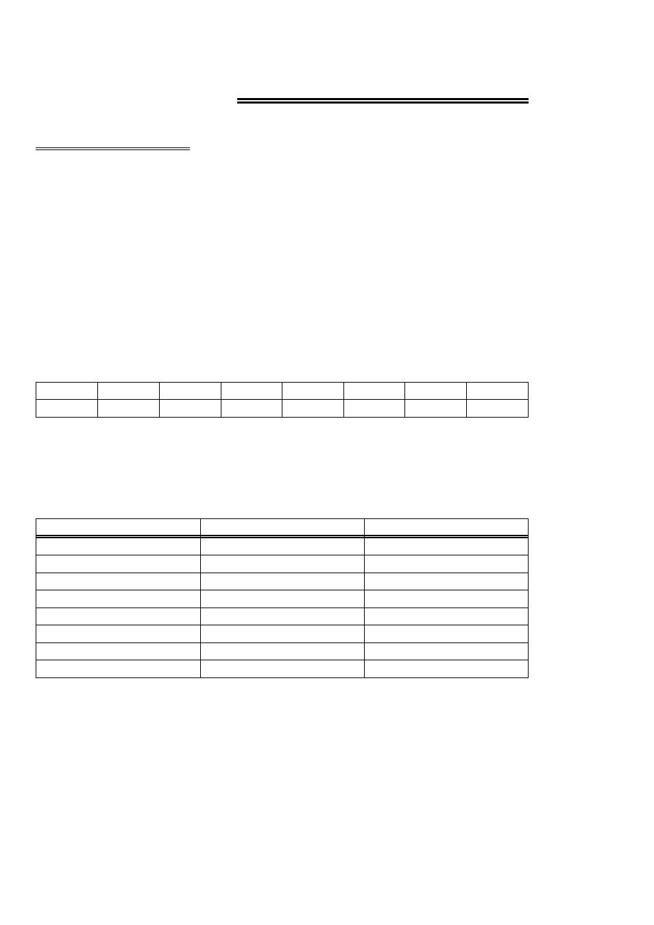
The register descriptions follow all follow the format:
A0
A1
A2
A3
A4
A5
A6
A7
0
1
2
3
4
5
6
7
Where the numbers along the top row are the bit positions within the 8-bit byte and
the numbers and symbols in the bottom row are the functions associated with that bit.
To write to or read from a register in decimal or HEX, the following weights apply:
80
128
7
40
64
6
20
32
5
10
16
4
8
8
3
4
4
2
2
2
1
1
1
0
HEX VALUE
DECIMAL VALUE
BIT POSITION
To write a control word or data to a register, the individual bits must be set to 0 or 1
then combined to form a byte.
The method of programming required to set/read bits from bytes is beyond the scope
of this manual.
6