5 low pass filters de-bounce inputs – Measurement Computing PC104-AC5 User Manual
Page 20
For Attenuation of 5:1 or less, no resistor should be less than 10K.
For Attenuation of greater than 5:1, no resistor should be less than 1K.
The CIO-TERMINAL has the circuitry on board to create custom voltage dividers. It
is a 16" by 4" screw terminal board with two 37-pin, D-type connectors and 56 screw
terminals (12 - 22 AWG). Designed for table top, wall, or rack mounting, the board
provides prototype, divider circuit, filter circuit and pull-up resistor positions which
you can use for your application.
5.5 LOW PASS FILTERS DE-BOUNCE INPUTS
A low-pass filter between a signal source and an A/D board attenuates higher than the
cut-off frequency, preventing them from entering the A/D board's analog or digital
input circuits.
The key term in a low pass filter circuit is cut-off frequency. The cut-off frequency is
that frequency above which no variation of voltage with respect to time may enter the
circuit. For example, if a low pass filter had a cut-off frequency of 30 Hz, the kind of
interference associated with line voltage (60 Hz) would be largely filtered out but a
signal of 25 Hz would pass.
Low-pass filters are often used to remove a switch-bounce noise signal from a switch
closure. The signal can be complex and have quite high frequency components
requiring a more sophisticated filter.
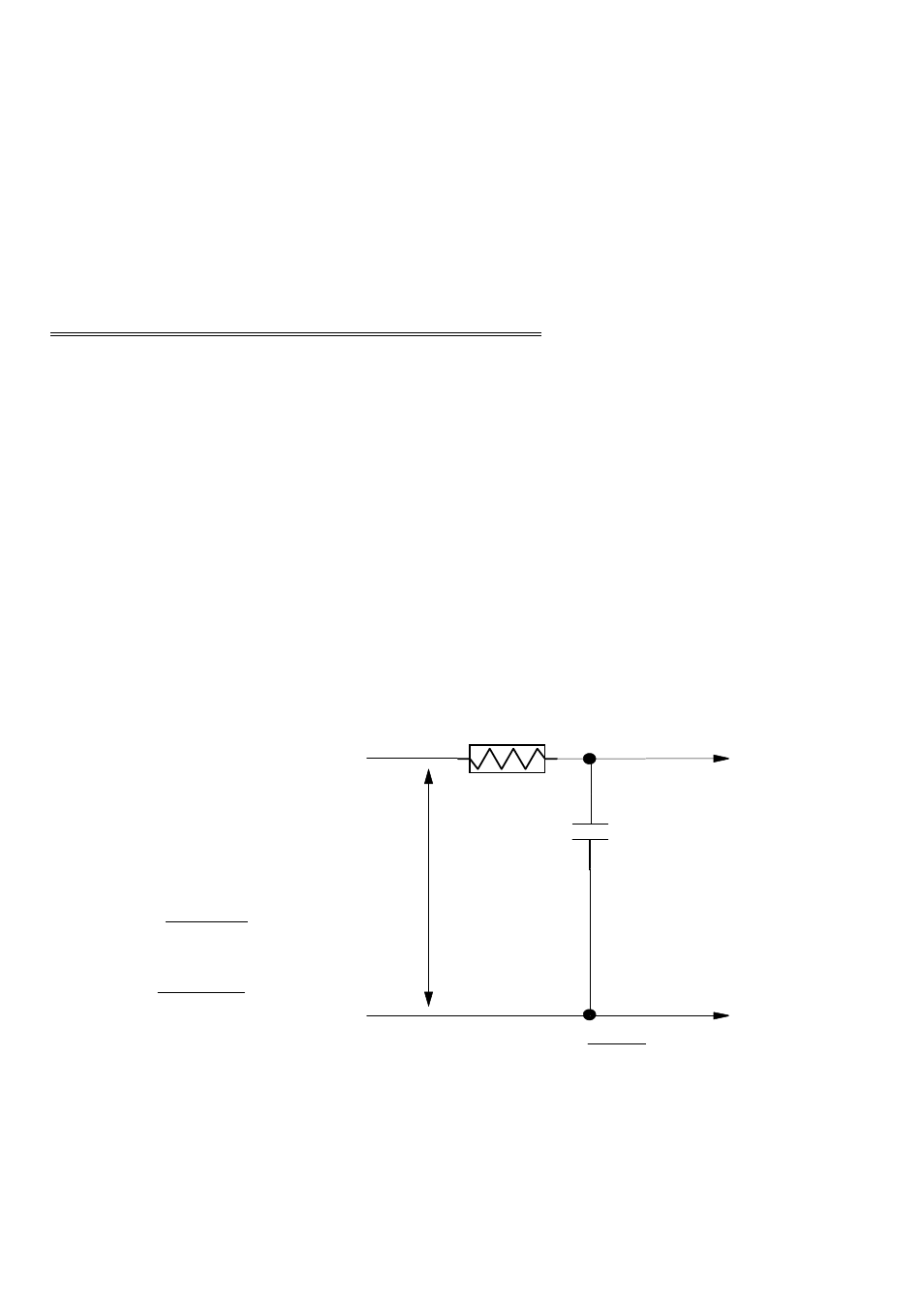
A simple low-pass filter can be
constructed from one resistor (R)
and one capacitor (C). The cut off
frequency is determined according
to the formula:
F
c
= 1
2*Pi*R*C
R = 1
2*Pi*C*F
c
Where Pi = 3.14...
R is in Ohms
C is in Farads
Fc is in cycles per second.
16
A/D Board
High Input
A/D Board
Low Input
Signal
High
Signal
Low
Signal
Volts
R
C
LOW PASS FILTER - Fc =
1
2*Pi*R*C