Measurement Computing PC104-AC5 User Manual
Page 17
The concept of voltage level of a PC104-AC5 in input mode is meaningless. Do not
connect a volt meter to the floating input of an PC104-AC5. It will show you nothing
of meaning. In input mode the PC104-AC5 is in 'high Z' or high impedance. If your
PC104-AC5 was connected to another input chip (the device you were controlling),
the inputs of that chip are left floating whenever the PC104-AC5 is in input mode.
If the inputs of the device you are controlling are left to float, they may float up or
down. Which way they float is dependent on the characteristics of the circuit and the
electrical environment; and is unpredictable This is why it often appears that the
PC104-AC5 has gone 'high' after power up. The result is that the controlled device
gets turned on.
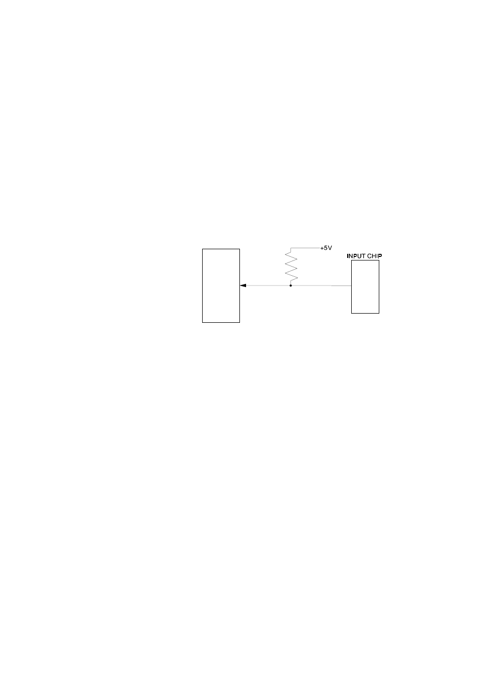
That is why you need pull up/down
resistors.
Shown here is one PC104-AC5
digital output with a pull-up
resistor attached.
The pull-up resistor provides a
reference to +5V while its value of
2200 ohms allows only about 2 mA
to flow through the circuit.
If the PC104-AC5 is reset and enters high impedance input, the line is pulled high. At
that point, both the PC104-AC5 AND the device being controlled will sense a high
signal.
If the PC104-AC5 is in output mode, the PC104-AC5 has more than enough power to
over ride the pull-up/down resistor's high signal and drive the line to 0 volts. If the
PC104-AC5 asserts a high signal, the pull up resistor guarantees that the line goes to
+5V.
A pull-down resistor accomplishes the same task except that the line is pulled low
when the PC104-AC5 is reset. The board has more than enough power to drive the
line high.
The PC104-AC5 board is equipped with positions for pull-up/down resistors Single
Inline Packages (SIPs). The positions are marked RN1 (Port A), RN2 (Port B) and
RN3 (Port C) and are located beside the connector P1.
13
8 2 C 5 5
E m u l a t e d
C i r c u i t