External trigger, External clock input/output – Measurement Computing E-1608 User Manual
Page 23
E-1608 User's Guide
Specifications
23
Parameter
Specification
Input high voltage threshold
2.0 V min
Input high voltage limit
5.5 V absolute max
Input low voltage threshold
0.8 V max
Input low voltage limit
–0.5 V absolute min
0 V recommended min
Output high voltage
3.8 V typ at no load
3.0 V min (IOH = –3 mA)
2.0 V min (IOH = –32 mA)
Output low voltage
0.15 V typ at no load
0.55 V max (IOL = 64 mA)
Power on and reset state
Input
Note 5:
This is the typical throughput when the device and host are both connected by Ethernet to the same
local network. The throughput can vary significantly, and typical throughput is not guaranteed if a
wireless connection is involved or data is sent over the internet.
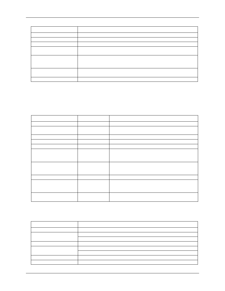
External trigger
Table 11. External trigger specifications
Parameter
Condition
Specification
Trigger source
External digital
TRIG
Trigger mode
Software-selectable
Edge or level sensitive: user configurable for CMOS
compatible rising or falling edge, high or low level.
Trigger latency
2 µs + 1 pacer clock cycle max
Trigger pulse width
1 µs min
Input type
Schmitt trigger, 47 kΩ pull-down to ground
Schmitt trigger hysteresis
1.01 V typ
0.6 V min
1.5 V max
Input high voltage threshold
2.43 V typ
1.9 V min
3.1 V max
Input high voltage limit
5.5 V absolute max
Input low voltage threshold
1.42 V typ
1.0 V min
2.0 V max
Input low voltage limit
–0.5 V absolute min
0 V recommended min
External clock input/output
Table 12. External clock I/O specifications
Parameter
Specification
Terminal names
AICKI, AICKO
Terminal types
AICKI: Input (receives A/D pacer clock from external source)
AICKO: Output (outputs internal A/D pacer clock)
Input clock rate
250 kHz max
Clock pulse width
AICKI: 1 µs min
AICKO: 1.8 µs min
Clock mode
Edge-sensitive, rising
Input type
Schmitt trigger, 47 kΩ pull-down to ground