Trigger input, Counter input, Power output – Measurement Computing E-1608 User Manual
Page 16: Ground
E-1608 User's Guide
Functional Details
16
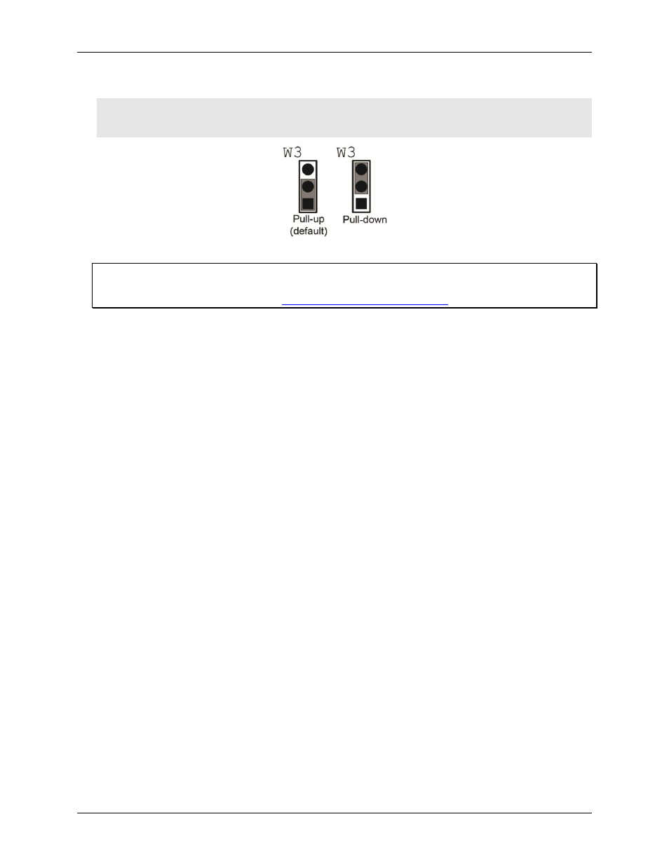
Figure 7 shows the jumper configured for pull-up and pull-down.
Caution! The discharge of static electricity can damage some electronic components. Before touching the
board, ground yourself using a wrist strap or touch the computer chassis or other grounded object
to eliminate any stored static charge.
Figure 7. W3 jumper configurations
For more information about digital signal connections
For general information about digital signal connections and digital I/O techniques, refer to the Guide to Signal
Connections (available on our web site
Trigger input
The
TRIG
terminal is an external digital trigger input. The trigger mode is software selectable for edge or level
sensitive.
Edge sensitive mode is configurable for rising or falling edge.
Level sensitive mode is configurable for high or low level.
The default setting at power up is edge sensitive, rising edge.
Counter input
The
CTR
terminal is a 32-bit event counter that can accept frequency inputs up to 10 MHz. The internal counter
increments when the TTL levels transition from low to high.
Power output
The
+VO
terminal can output up to 10 mA maximum. You can use this terminal to supply power to external
devices or circuitry.
Ground
The analog ground (
AGND
) terminals provide a common ground for all analog channels.
The digital ground (
GND
) terminals provide a common ground for the digital, counter, timer, and clock
channels and the power terminal.