Measurement Computing CIO-DAS08-PGH User Manual
Page 7
The following table shows some typical interrupt assignments on a PC. The CIO-DAS08-PGx use interrupt levels 2 through 7.
The levels most often available are 5 and 7.
Table 1-2. IRQ Assignments
LPT
IRQ7
UNASSIGNED
IRQ15
FLOPPY DISK
IRQ6
HARD DISK
IRQ14
HARD DISK (XT) or LPT (AT)
IRQ5
80287 NUMERIC CO-P
IRQ13
COM OR SDLC
IRQ4
UNASSIGNED
IRQ12
COM OR SDLC
IRQ3
UNASSIGNED
IRQ11
RESERVED (XT)
INT 8-15 (AT)
IRQ2
UNASSIGNED
IRQ10
KEYBOARD
IRQ1
RE-DIRECTED TO IRQ2
IRQ9
TIMER
IRQ0 (AT)
REAL TIME CLOCK (AT)
IRQ8
PARITY
NMI
DESCRIPTION
NAME
DESCRIPTION
NAME
NOTE: IRQ8-15 are AT only.
1.2.3 XTAL/PC Bus Clock Jumper
The A/D pacer clock sources for the MetraByte DAS-8PGA differs from the DAS-8.
The source for the DAS-8PGA is fixed at 1 MHz while the source for the DAS-8 gets
its clock pulse from the PC Bus Clock.
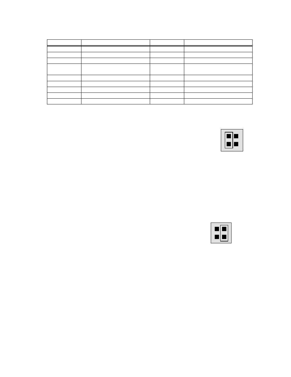
The CIO-DAS08-PGx pacer clock is selected by jumper to satisfy software written
for either board (Figure 1-3). The default choice for this jumper is the 1 MHz
position. You can alternately select the PC Bus Clock as the source for the A/D pacer
clock.
Figure 1-3. Pacer Clock Select Jumper
1.2.4 Wait State
A wait state can be enabled on the CIO-DAS08-PGx by selecting WAIT STATE ON
at the jumper provided on the board. Enabling the wait state causes the personal
computer's bus transfer rate to slow down for board reads and writes ..
The wait state jumper is provided in case your computer ever has an I/O bus transfer
rate which is too fast for the CIO-DAS08-PGA. If your board were to fail sporadically
in random ways, try selecting the wait state ON.
Figure 1-4. Wait State Jumper Block
1.2.5 Installing The CIO-DAS08-PGx In The Computer
1. Turn the power off.
2. Remove the cover of your computer. Please be careful not to dislodge any of the cables installed on the boards in your
computer as you slide the cover off.
3. Locate an empty expansion slot in your computer.
4. Push the board firmly down into the expansion bus connector. If it is not seated fully it may fail to work and could short circuit
the PC bus power onto a PC bus signal. This could damage the motherboard in your PC as well as the board.
3
1 MHz
CLK
BUS
CLOCK SOURCE JUMPER - For a
standard DAS-8PGA 1 MHz A/D
Pacer Clock, place the jumper on the
two leftmost pins. For a DAS-8 type
A/D Pacer from PC Bus Clk, place the
jumper on the two rightmost pins.
O
N
O
F
F
WAIT
STATE
wait state is not selected on this
jumper block. For a wait state,
place the jumper on the two
leftmost pins.
WAIT STATE JUMPER BLOCK - A