Measurement Computing CIO-DAS08-PGH User Manual
Page 21
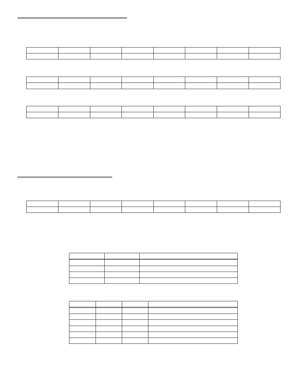
4.5 COUNTER LOAD & READ REGISTERS
COUNTER 0
BASE ADDRESS + 4 (Read / Write)
D0
D1
D2
D3
D4
D5
D6
D7
0
1
2
3
4
5
6
7
COUNTER 1
BASE ADDRESS + 5 (Read / Write)
D0
D1
D2
D3
D4
D5
D6
D7
0
1
2
3
4
5
6
7
COUNTER 2
BASE ADDRESS + 6 (Read / Write)
D0
D1
D2
D3
D4
D5
D6
D7
0
1
2
3
4
5
6
7
The data in the counter read register, and the action taken on the data in a counter load register, is wholly dependent upon the
control code written to the control register.
The counters are 16-bit counters, each with an 8-bit window, the read / load register. Data is shifted into and out of the 16-bit
counters through these 8-bit windows according to the control byte.
You will need an 8254 data sheet if you want to program the 8254 directly at the register level.
4.6 COUNTER CONTROL REGISTER
BASE ADDRESS + 7 (Write Only)
BCD
M0
M1
M2
RL0
RL1
SC0
SC1
0
1
2
3
4
5
6
7
WRITE
SC1 to SC0 are the counter select bits. They are binary coded between 0 and 2.
RL1 to RL0 are the read and load control bits:
Read/load low the high byte (word transfer)
1
1
Read/load low byte
0
1
Read/load high byte
1
0
Latch Counter
0
0
OPERATION
RL0
RL1
M2 to M0 are the counter control operation type bits:
Hardware triggered strobe
1
0
1
Software triggered strobe
0
0
1
Square wave generator
1
1
0
Rate generator
0
1
0
Programmable one-shot
1
0
0
Change on terminal count
0
0
0
OPERATION TYPE
M0
M1
M2
BCD = 0 then counter data is 16-bit binary. (65,535 max)
17