Measurement Computing CIO-DAS08-PGH User Manual
Page 14
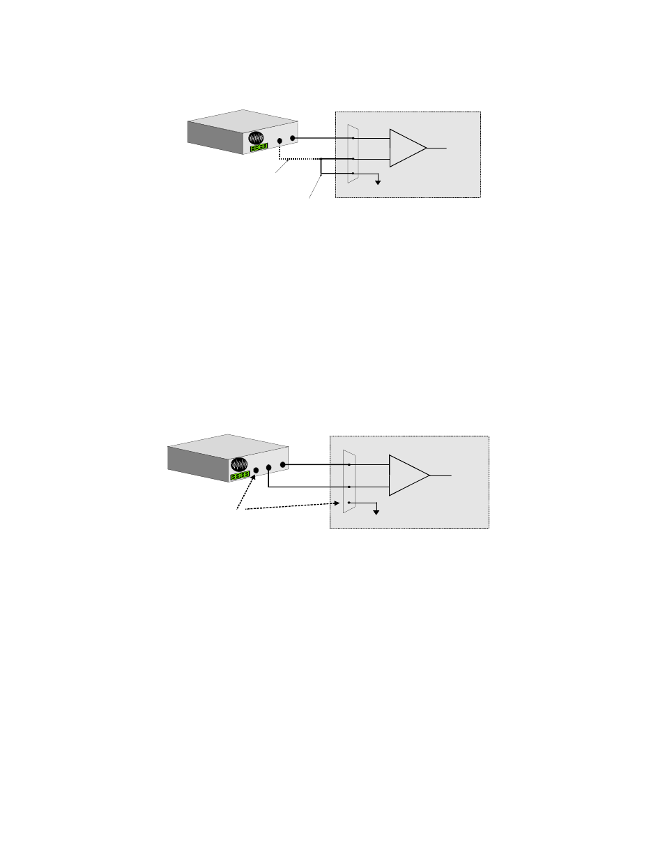
3.2.2 Common Ground / Differential Inputs
The use of differential inputs to monitor a signal source with a common ground is a acceptable configuration though it requires
more wiring and offers fewer channels than selecting a single-ended configuration. Figure 3-5 below shows the recommended
connections in this configuration.
Figure 3-5. Common Ground / Differential Inputs
3.2.3 Common Mode Voltage < +/-10V/Single-Ended Inputs
This is not a recommended configuration. In fact, the phrase common mode has no meaning in a single-ended system and this case
would be better described as a system with offset grounds. However, you can try this configuration. No system damage should
occur and depending on the overall accuracy you require, you may receive acceptable results.
3.2.4 Common Mode Voltage < +/-10V/Differential Inputs
Systems with varying ground potentials should always be monitored in the differential mode. Care is required to assure that the
sum of the input signal and the ground differential (referred to as the common mode voltage) does not exceed the common mode
range of the A/D board (+/-10V on the CIO-DAS08-PGx). The diagram below show recommended connections in this
configuration.
Figure 3-6. Common Mode Voltage < +/-10V/Differential Inputs
10
+
-
In p u t
A m p
To A /D
A /D B o a rd
I/O
C o n n e c to r
LL G N D
C H H igh
C H Low
S ig
n a l
S
o urce
w ith
C o m
m o n
G n d
O ptio nal w ire
since signa l source
and A /D bo ard sha re
com m on g round
R equ ired connection
of L L G N D to C H Low
S ign a l s o u rc e an d A /D bo a rd
s ha ring c o m m o n g ro u nd c on n e c te d
to d iffe re n tia l in pu t.
+
-
In p ut
A m p
To A /D
A /D B o a rd
I/O
C o n n ec to r
L L G N D
C H H ig h
C H L o w
S ig n
al S o
u rce
w i
th C o
m m o
n
M o d
e Vo
ltage
S ig n a l s o u rc e a n d A /D b o a rd
w ith c o m m o n m o d e v o lta g e
c o n n e c te d to a d iffe re n tia l in p u t.
G N D
T he vo ltag e d ifferen tia l
b etw ee n the s e groun d s,
a dde d to the m a x im u m
in p ut s ig na l m ust s ta y
w ithin +/-10 V