2 wiring configurations – Measurement Computing CIO-DAS08-PGH User Manual
Page 13
3.1.9 Board and Signal Source Have Isolated Grounds
Some signal sources will already be electrically isolated from the board. Figure 3-4 shows a typical isolated ground system. These
signal sources are often battery powered, or are fairly expensive pieces of equipment (since isolation can be expensive), isolated
ground systems provide excellent performance, but require some extra effort during connections to assure optimum performance
is obtained. Please refer to the following sections for further details.
3.2 WIRING CONFIGURATIONS
Combining all the grounding and input type possibilities provides us with the following potential connection configurations. Th e
combinations along with our recommendations on usage are shown in Table 3-1 below.
Table 3-1. Analog Input Configuration Recommendations
Recommended
Differential Inputs
Already Isolated
Grounds
Acceptable
Single-ended Inputs
Already Isolated Grounds
Unacceptable without
adding Isolation
Differential Inputs
Common Mode
Voltage > +/-10V
Unacceptable without
adding Isolation
Single-Ended Inputs
Common Mode
Voltage > +/- 10V
Recommended
Differential Inputs
Common Mode
Voltage < +/-10V
Not Recommended
Single-Ended Inputs
Common Mode
Voltage < +/-10V
Acceptable
Differential Inputs
Common Ground
Recommended
Single-Ended Inputs
Common Ground
OUR VIEW
INPUT
CONFIGURATION
GROUND
CATEGORY
The following sections depicts recommended input wiring schemes for each of the seven possible input configuration/grounding
combinations.
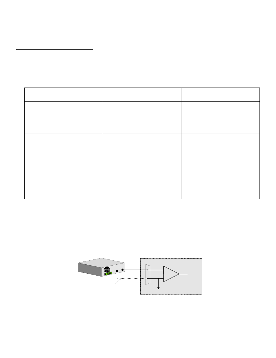
3.2.1 Common Ground / Single-Ended Inputs
Single-ended is the recommended configuration for common ground connections. However, if some of your inputs are common
ground and some are not, we recommend you use the differential mode. There is no performance penalty (other than loss of
channels) for using a differential input to measure a common ground signal source. However the reverse is not true. Figure 3-4
below shows a recommended connection diagram for a common ground / single-ended input system.
Figure 3-4. Common Ground / Single-Ended Inputs
9
+
-
In p u t
A m p
To A /D
A /D B o a rd
I/O
C o n n e c to r
LL G N D
C H IN
S ig
n a l
S
o u rc e
w ith
C
o m m
o n G
n d
O p tio nal w ire
since sig na l sou rce
and A /D bo ard sh are
com m o n g round
S ig n a l s o urc e an d A /D b o a rd
s h a rin g c om m o n gro u n d c o n n e c te d
to s in g le -en d ed inp u t.