Measurement Computing CIO-DAS08-PGH User Manual
Page 6
1.2 HARDWARE INSTALLATION
1.2.1 Base Address
The base address of the CIO-DAS08-PGx is set by switching a bank of DIP
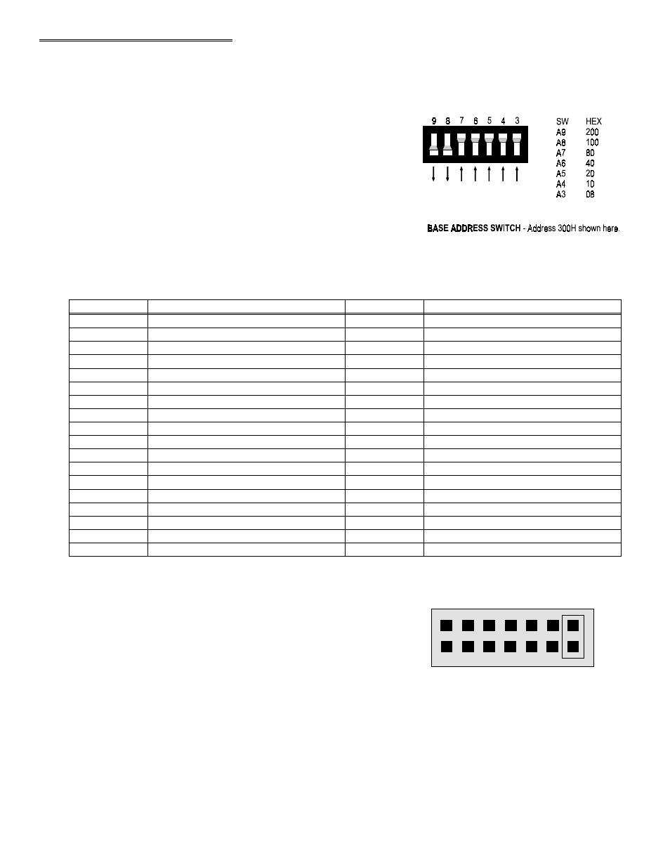
switches on the board (Figure 1-1). This bank of switches is labeled
ADDRESS and numbered 9 to 3.
Ignore the word ON and the numbers printed on the switch
The switch works by adding up the weights of individual switches to make a
base address. A 'weight' is active when the switch is down. Shown here,
switches 9 and 8 are down, all others are up. Weights 200H and 100H are
active, equaling 300H base address. The board is shipped with this default
address selected. If this address is already in use on your computer, select a
different address.
Figure 1-1. Base address Select Switches
Table 1-1 lists the address ranges for the PC computer.
Table 1-1. Base Addresses
SERIAL PORT
3F8-3FF
EGA
2B0-2BF
FLOPPY DISK
3F0-3F7
PARALLEL PRINTER
270-27F
SERIAL PORT
3E8-3EF
ALT BUS MOUSE
23C-23F
CGA
3D0-3DF
BUS MOUSE
238-23B
EGA
3C0-3CF
EXPANSION UNIT (XT)
210-21F
PARALLEL PRINTER
3BC-3BF
GAME CONTROL
200-20F
MDA
3B0-3BB
HARD DISK (AT)
1F0-1FF
SDLC
3A0-3AF
80287 NUMERIC CO-P (AT)
0F0-0FF
SDLC
380-38F
8237 #2 (AT)
0C0-0DF
PARALLEL PRINTER
378-37F
NMI MASK (XT)
0A0-0AF
HARD DISK (XT)
320-32F
8259 PIC #2 (AT)
0A0-0A1
PROTOTYPE CARD
310-31F
DMA PAGE REGISTERS
080-08F
PROTOTYPE CARD
300-30F
CMOS RAM & NMI MASK (AT)
070-071
SERIAL PORT
2F8-2FF
8742 CONTROLLER (AT)
060-064
SERIAL PORT
2E8-2EF
8255 PPI (XT)
060-063
GPIB (AT)
2E0-2E7
8253 TIMER
040-043
EGA
2D0-2DF
8259 PIC #1
020-021
EGA
2C0-2CF
8237 DMA #1
000-00F
FUNCTION
HEX RANGE
FUNCTION
HEX RANGE
1.2.2 Interrupt Level Select
The interrupt jumper need only be set if the software you are using
requires it. If you do set the interrupt jumper, please check your PC's
current configuration for interrupt conflicts, and do not use IR2 in PC/AT
class machines (or higher).
There is a jumper block on the CIO-DAS08-PGx located just above the
PC bus interface (gold pins). The factory default setting is that no
interrupt level is set. The jumper is in the 'X' position (Figure 1-2).
If you need to pace conversions through hardware (either the on - board
pacer or an external clock), move this jumper to one of the other positions
(see table 1-2).
Figure 1-2. Interrupt Select Jumper Block
2
2
3
4
5
6
7 X
INTERRUPT JUMPER BLOCK - Jumper in
X position = No IRQ.