3 hardware installation – Measurement Computing CIO-DAS08-AOH User Manual
Page 6
3 HARDWARE INSTALLATION
The CIO-DAS08-AOx has three banks of switches and three jumper blocks which must be set before installing the board in your
computer.
3.1 BASE ADDRESS
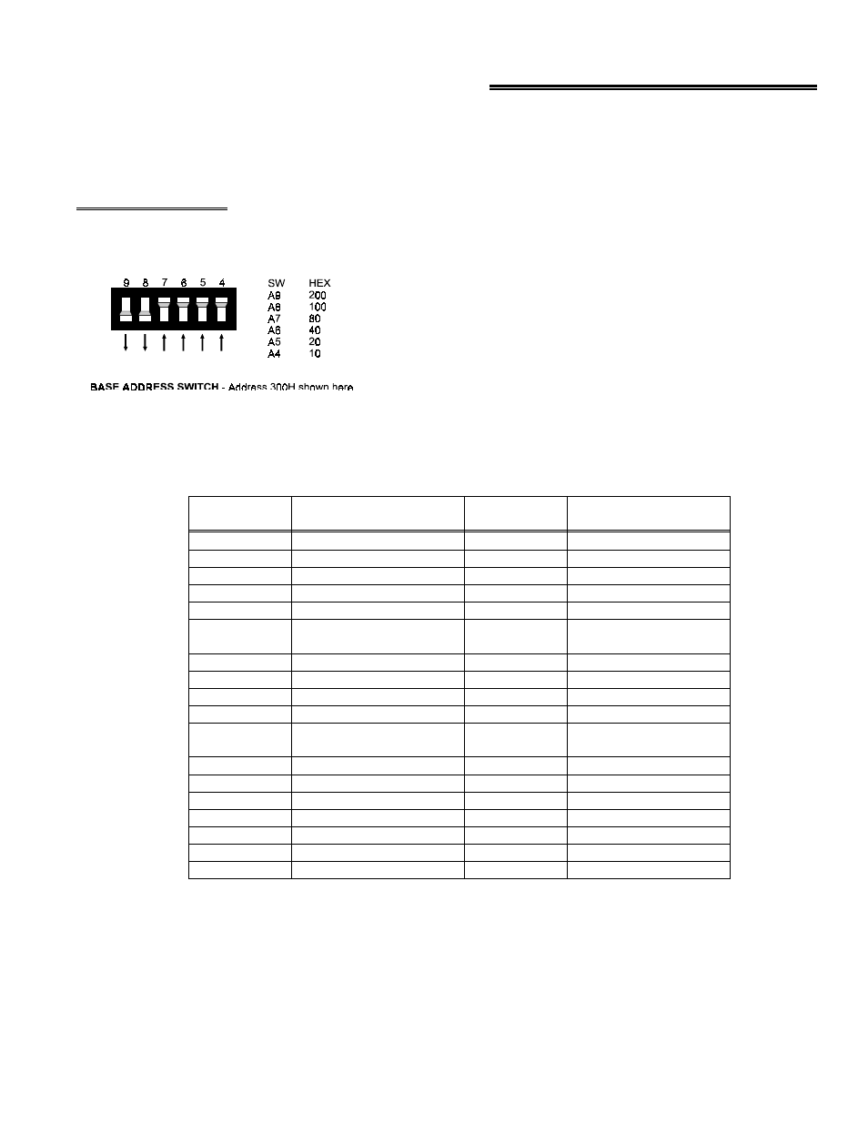
The base address of the CIO-DAS08-AOx is set by switching a bank
of DIP switches on the board (Figure 3-1). This bank of switches is
labeled ADDRESS and numbered 9 to 4.
Ignore the word ON and the numbers printed on the switch
The switch works by adding up the weights of individual switches to
make a base address. A 'weight' is active when the switch is down.
Shown to the right, switches 9 and 8 are down, all others are up.
Weights 200h and 100h are active, equaling 300h base address. Refer
to Table 1-1 for a list of standard PC addresses.
Figure 3-1. Base Address Switches
Table 3-1.
Standard PC I/O Addresses
SERIAL PORT
3F8-3FF
EGA
2B0-2BF
FLOPPY DISK
3F0-3F7
PARALLEL PRINTER
270-27F
SERIAL PORT
3E8-3EF
ALT BUS MOUSE
23C-23F
CGA
3D0-3DF
BUS MOUSE
238-23B
EGA
3C0-3CF
EXPANSION UNIT (XT)
210-21F
PARALLEL PRINTER
3BC-3BF
GAME CONTROL
200-20F
MDA
3B0-3BB
HARD DISK (AT)
1F0-1FF
SDLC
3A0-3AF
80287 NUMERIC CO-P
(AT)
0F0-0FF
SDLC
380-38F
8237 #2 (AT)
0C0-0DF
PARALLEL PRINTER
378-37F
NMI MASK (XT)
0A0-0AF
HARD DISK (XT)
320-32F
8259 PIC #2 (AT)
0A0-0A1
PROTOTTYPE CARD
310-31F
DMA PAGE REGISTERS
080-08F
PROTOTYPE CARD
300-30F
CMOS RAM & NMI
MASK (AT)
070-071
SERIAL PORT
2F8-2FF
8742 CONTROLLER (AT)
060-064
SERIAL PORT
2E8-2EF
8255 PPI (XT)
060-063
GPIB (AT)
2E0-2E7
8253 TIMER
040-043
EGA
2D0-2DF
8259 PIC #1
020-021
EGA
2C0-2CF
8237 DMA #1
000-00F
FUNCTION
ADDRESS
RANGE
FUNCTION
ADDRESS
RANGE
2