Measurement Computing CIO-DAS08-AOH User Manual
Page 21
6.10 82C55 CONTROL & DATA REGISTERS
The 24 bits of digital I/O is composed of one 82C55 parallel I/O chip which contains three data and one control register
occupying four consecutive I/O locations.
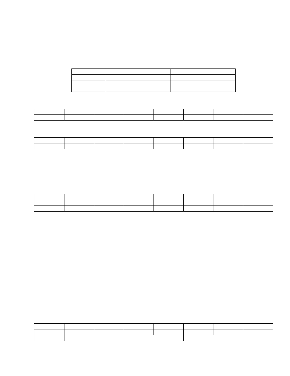
In summary form, the registers and their function are listed on the following table. Within each register are eight bits which
may constitute a byte of data or they may be eight individual bit set/read functions.
Configure 82C55 #1
None. No read back on 82C55
BASE + 15
Port C Output
Port C Input
BASE + 14
Port B Output
Port B Input
BASE + 13
Port A Output
Port A Input of 82C55 #1
BASE + 12
PORT A DATA
BASE ADDRESS +12 (Read / Write)
A0
A1
A2
A3
A4
A5
A6
A7
0
1
2
3
4
5
6
7
PORT B DATA
BASE ADDRESS + 13 (Read / Write)
B0
B1
B2
B3
B4
B5
B6
B7
0
1
2
3
4
5
6
7
Ports A & B may be programmed as input or output. Each is written to and read from in bytes, although for control and
monitoring purposes the individual bits are used.
Bit set/reset and bit read functions require that unwanted bits be masked out of reads and ORed into writes.
PORT C DATA
BASE ADDRESS + 14 (Read / Write)
CL0
CL1
CL2
CL3
CH0
CH1
CH2
CH3
C0
C1
C2
C3
C4
C5
C6
C7
0
1
2
3
4
5
6
7
Port C may be used as one 8-bit port of either input or output, or it may be split into two, 4-bit ports which independently may
be input or output. The notation for the upper 4-bit port is CH3 - CH0, and for the lower, CL3 - CL0.
Although it may be split, every read and write to port C carries eight bits of data so unwanted information must be ANDed out
of reads, and writes must be ORed with the current status of the other port.
OUTPUT PORTS
In 82C55 mode 0 configuration, ports configured for output hold the output data written to them. This output byte may be
read back by reading a port configured for output.
INPUT PORTS
In 82C55 mode 0 configuration, ports configured for input read the state of the input lines at the moment the read is executed,
transitions are not latched.
For information on modes 1 (strobed I/O) and 2 (bi-directional strobed I/O), you will need to acquire an Intel or AMD data
book and see the 82C55 data sheet.
82C55 CONTROL REGISTER
BASE ADDRESS + 15 (Write Only)
Group B
Group A
CL
B
M1
CU
A
M2
M3
MS
0
1
2
3
4
5
6
7
17