5 signal connection, 1 analog connector diagram, 2 differential inputs – Measurement Computing CIO-DAS08-AOH User Manual
Page 11
5 SIGNAL CONNECTION
Making correct signal connections is one of the most important aspects of applying a data acquisition board. Failure to properly
connect signals is the most common reason for calls to technical support. Usually, a problem can be located by cross-checking the
wiring against the connector diagram
5.1 ANALOG CONNECTOR DIAGRAM
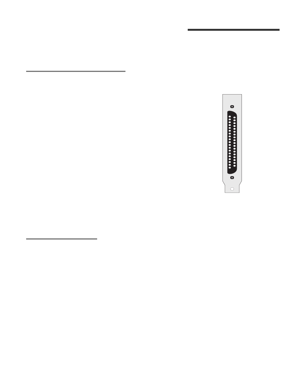
The CIO-DAS08-AOx analog connector is a male 37-pin D-type connector,
accessible from the rear of the PC through the expansion backplate.
The connector accepts female 37-pin D-type connectors, such as those on
the C73FF-2, 2 foot cable with connectors.
If frequent changes to signal connections or signal conditioning is required,
please refer to the information on the CIO-TERMINAL and CIO-MINI37
screw terminal boards, CIO-EXP32, 32 channel analog MUX/AMP.
Isolation amplifiers may be mounted using the ISO-RACK08 and 5B
isolation modules.
Figure 4-1. Analog Connector Diagram
5.2 DIFFERENTIAL INPUTS
The CIO-DAS08-AOx has eight differential analog inputs. For a detailed description of differential vs. single-ended analog
inputs, turn to the section of this manual on Analog Electronics.
Briefly, differential inputs are three-wire analog hookups consisting of a signal-high, a signal-low, and a chassis ground. The
benefits of differential inputs are the ability to reject noise, and the ability to eliminate ground loops or potentials between
signal low and chassis ground.
Although differential inputs are often preferable to single ended inputs, there are occasions when the floating nature of a
differential input can cause input reading difficulties. In those cases, the CIO-DAS08-AOx inputs can be converted to
modified differential.
Examine the diagram of the CIO-DAS08-AOx board. A position for an optional Single Inline Package (SIP) of resistors is
located near the 37-pin connector. Installing the SIP converts the analog inputs from fully differential to modified differential
with a resistive reference to ground. A SIP resistor network is included with the board for this purpose.
7
CH 0 LOW 19
CH 1 LOW 18
CH 2 LOW 17
CH 3 LOW 16
CH 4 LOW 15
CH 5 LOW 14
CH 6 LOW 13
CH 7 LOW 12
L.L. GND 11
OP4 10
OP3
9
OP2
8
OP1
7
OUT 2
6
OUT 1
5
CLK 1
4
OUT 0
3
CLK 0
2
DAC I OUT
1
37 CH 0 HIGH
36 CH 1 HIGH
35 CH 2 HIGH
34 CH 3 HIGH
33 CH 4 HIGH
32 CH 5 HIGH
31 CH 6 HIGH
30 CH 7 HIGH
29 PC BUS +5
28 DIGITAL GND
27 IP3
26 IP2
25 IP1
24 IR INPUT
23 GATE 2
22 GATE 1
21 D/A LLGND
20 DAC 0 OUT
37 PIN CONNECTOR