Measurement Computing CIO-DAS08-AOH User Manual
Page 26
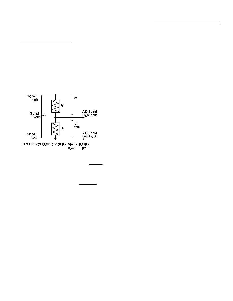
8 APPLICATION NOTES
8.1 VOLTAGE DIVIDERS
If you wish to measure a signal which varies over a range greater than the input range of an analog or digital input, a voltage
divider must be used to drop the voltage of the input signal to the level the analog or digital input can measure.
A voltage divider takes advantage of Ohm's law, which states,
Voltage = Current * Resistance
and Kirkoff's voltage law which states,
The sum of the voltage drops around a circuit will be equal to the voltage drop for the entire circuit.
Implied in the above is that any variation in the voltage drop for the
circuit as a whole will have a proportional variation in all the voltage
drops in the circuit.
In a voltage divider, the voltage across one resistor in a circuit is
proportional to the voltage across the total resistance in the circuit.
The object in using a voltage divider is to choose two resistors with
the proper proportions relative to the full scale of the analog or
digital input and the maximum signal voltage.
Dropping a voltage proportionally is called attenuation. The formula
for attenuation is:
For a given attenuation, pick a handy resisitor
and call it R2, the use this formula to calculate
R1.
R1 = (A-1) * R2
For example, if the signal varies between 0 and
20 volts and you wish to measure that with an
analog input with a full scale range of 0 to 10
volts, the Attenuation is 2:1 or just 2.
2 = 10K + 10K
10K
The variable attenuation is the proportional
difference between the signal voltage max and
the full scale of the analog input.
Attenuation = R1 + R2
R2
Digital inputs may require the use of voltage dividers. For example, if you wish to input a digital signal that is at 0 volts when
off and 24 volts when on, you cannot connect that directly to the CIO-AD digital inputs. The voltage must be dropped to 5
volts max when on. The attenuation is 24:5 or 4.8. Use the equation above to find an appropriate R1 if R2 is 1K. Remember
that a TTL input is 'on' when the input voltage is greater than 2.5 volts.
IMPORTANT NOTE
The resistors, R1 and R2, are going to dissipate all the power in the divider circuit according to the equation
Current (I) = Voltage / Resistance and power (W) = I
2
* R. The higher the value of the resistance (R1 + R2)
the less power dissipated by the divider circuit. Here are two simple rules:
For Attenuation of 5:1 or less, no resistor should be less than 10K.
For Attenuation of greater than 5:1, no resistor should be less than 1K.
22