Appendix 5: sample layouts – Infloor Standard Electric Cable User Manual
Page 20
20
Infloor Installation Manual
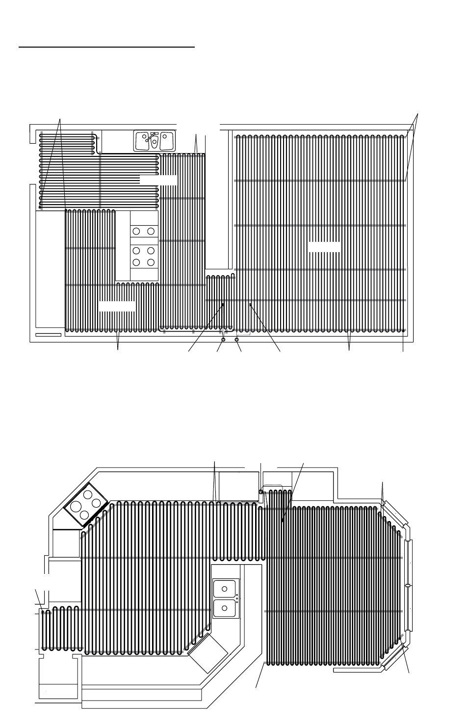
Appendix 5: Sample Layouts
Sink
C
oun
ter t
op and c
abinetr
y
C
oun
ter t
op and c
abinetr
y
Island
Zone 1a
Zone 1b
Zone 2
Zone 1
Control
Control
Zone 2
Control
Zone 2
Sensor
Zone 1
Sensor
1 spool
70 sq . ft .
2-1/2” spacing
1 spool
240 sq . ft .
3” spacing
Spool
termination
1 spool
120 sq . ft .
2-1/2” spacing
Strap
Range
Counter/cabinetry
Counter and cabinetry
Sink
Pantry
Dish-
washer
Microwave
Floor
Sensor
Spool termination
Spool
termination
Spool
termination
1 spool
120 sq . ft .
3” spacing
1 spool
112 sq . ft .
2” spacing
Strap
Kitchen and Family Room (normal heat loss, slab on grade with insulation)
Two zones, 240 volts: Kitchen/Zone 1a = 1 spool, 70 sq .ft ., 2-1/2” spacing;
Zone 1b = 1 spool; 120 sq . ft ., 2-1/2” spacing .
Family Room/Zone 2 = 1 spool, 240 sq . ft ., 3” spacing
190 ft . of strap, or eight 25-ft . rolls .
Kitchen and SunRoom (normal and high heat loss, framed floor construction)
One zone, 240 volts: Kitchen = 1 spool; 120 sq . ft .; 3” spacing .
Sunroom = 1 spool; 112 sq . ft .; 2” spacing .
104 ft . of strap, or five 25-ft . rolls .