Phase 6: finish wiring, New construction, Existing construction – Infloor Standard Electric Cable User Manual
Page 12
12
Infloor Installation Manual
Phase 6: Finish Wiring
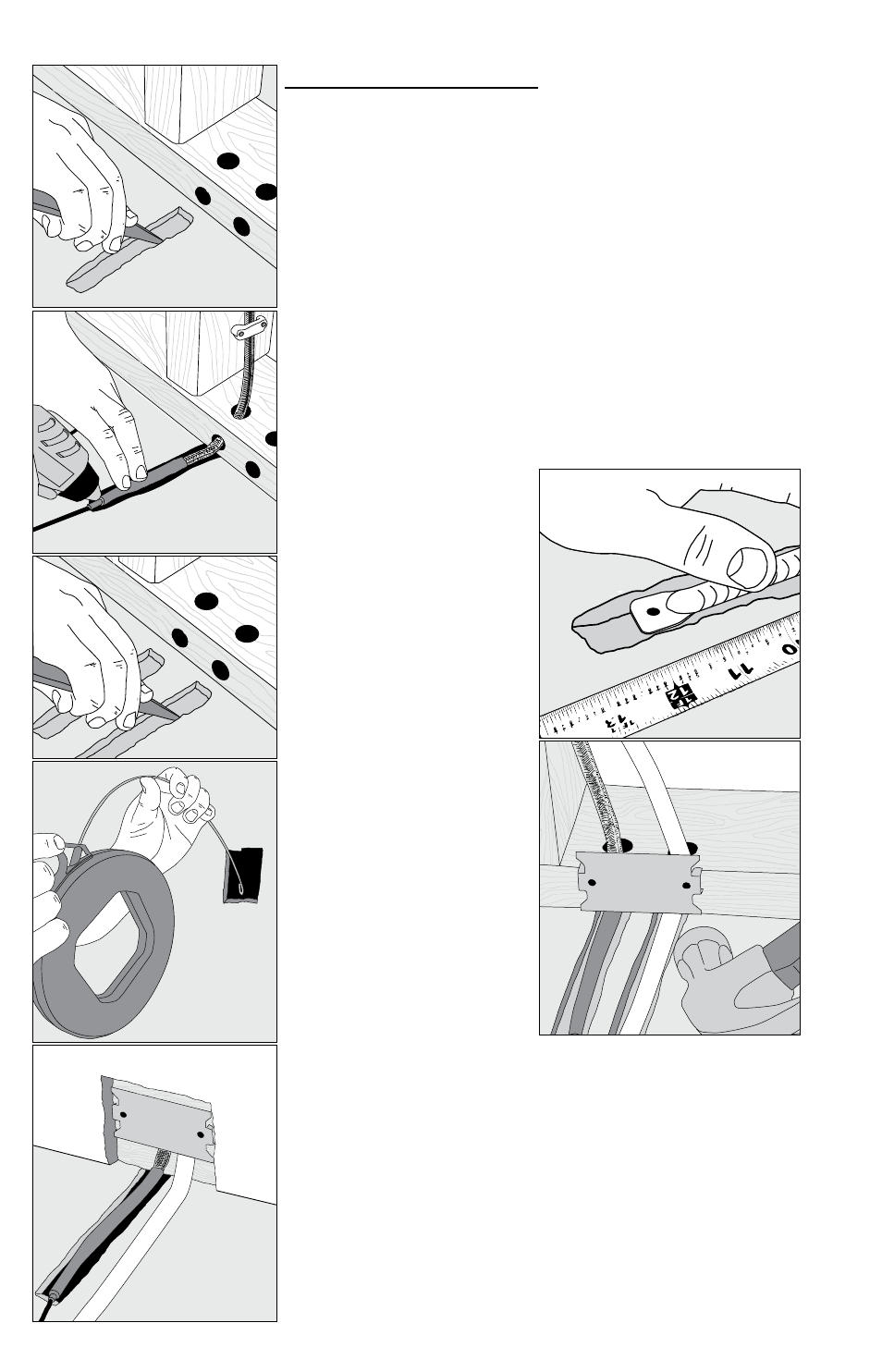
STEP 6.1 Chisel a channel into the floor to lay the factory splice into . This
will ensure the splice does not create a high-spot in the floor . CAUTION:
The power lead splice MUST BE FULLY EMBEDDED IN the mortar bed and
never bend the factory splices. NEVER allow any part of the splice or
heating cable to enter a wall or drop through the subfloor.
New Construction
STEP 6.2 Feed the power leads from the cable up through the hole drilled
in the baseplate, or up into the conduit to the control electrical box
(or junction box if one was used) .
STEP 6.3 Secure the power lead splice into the chiseled channels with
hot-glue .
STEP 6.4 Below the control, or wherever the floor sensor tube is to be
located, measure at least 1ft . into the heated area . Mark the spot where the
sensor tube will be attached to the floor . Be sure to locate the sensor tube
exactly between two of the heating cables .
STEP 6.5 To make sure the sensor tube does not create a high spot in the
floor, chisel a channel into the floor and lay the sensor tube into the chan-
nel, secure the sensor tube .
STEP 6.6 Drill another hole into
the baseplate, if needed, to feed the
sensor tube up to the control box .
Feed the thermostat sensor down
the sensor tube . Finish by securing
a steel nail plate over the power
lead(s) and sensor tube to protect
them against baseboard nails later .
STEP 6.7 If it was necessary to end
a power lead at a junction box, feed
14- or 12-gauge electrical wire from
this box to the control box .
Tip: If more than one cable was
installed, label the ends of the power
leads with a brief description as to
which area they supply power . Use
tape to label them “Cable 1,” “Cable
2,” “Kitchen,” “Bath,” or similar . This
will make it easier to identify the
leads later on . Take photos of the
installation . This will provide a use-
ful record for any future needs .
Existing Construction
STEP 6.8 Use a fish tape to pull the
power leads up the wall to the con-
trol electrical box (or junction box if
one was used) .
STEP 6.9 Secure the power lead fac-
tory splice into the chisled channel
with hot-glue (see photo for Step 6 .3) .
STEP 6.10 Below the control, or
wherever the floor sensor tube is
to be located, measure at least 1ft .
into the heated area . Mark the spot
where the sensor tube will be attached to the floor . Be sure to locate the
sensor tube exactly between two of the heating cables . To make sure the
sensor tube does not create a high spot in the floor, chisel a channel into
the floor and lay the sensor tube into the channel, secure the sensor tube .
STEP 6.11 Feed thermostat sensor into sensor tube, pull sensor tube up the
wall to the control electrical box, and finish by securing a steel nail plate over
the power lead(s) and sensor tube to protect them against baseboard nails .
STEP 6.12 If it was necessary to end a power lead at a junction box, feed 14-
or 12-gauge electrical wire from this box to the control box .
Tip: If more than one cable was installed, label the power leads with a
brief description as to which area they supply power . Use tape to label them
“Cable 1,” “Cable 2,” or “Kitchen,” “Bath,” or similar . This will make it easier to
identify the leads later on . Take photos of the installation . This will provide a
useful record for any future needs .
STEP 6.1
STEP 6.3
STEP 6.4
STEP 6.8
STEP 6.5
STEP 6.6
STEP 6.11