Phase 7: install the control, Phase 8: install the floor coverings, Phase 9: install insulation – Infloor Standard Electric Cable User Manual
Page 13: Phase 10: system operation, Step 7.3
Infloor Installation Manual
13
Phase 7: Install the Control
STEP 7.1 Read and follow the instructions that come with
the Infloor controls .
STEP 7.2 Refer to the wiring diagrams in this manual for
different voltages and applications .
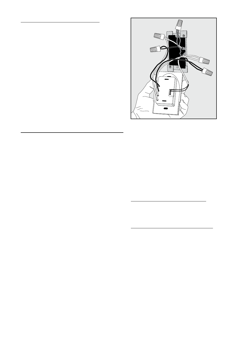
STEP 7.3 Install the electrical box for the control, if this has
not already been done . Connect the power leads from the
cable (or the electrical wiring coming from junction boxes)
to the “LOAD” side of the control . Connect the incoming
power to the “LINE” side of the control . Connect the sensor
wires to the sensor terminals on the control . Connect the
ground leads from the system to the ground wire from the
incoming power .
STEP 7.4 Install the control into its electrical box and turn
the circuit breaker on to power the system . Test the system
and control for
several cycles . It should allow the heating cables to heat up
correctly . Note: Consider placing a loose tile over the sensor
tip to simulate warming the floor and allow the sensor to
register this on the control .
STEP 7.5 Retain all instruction sheets and warranties .
Phase 8: Install the Floor Coverings
STEP 8.1 Make a Final Inspection of the Installation . Inspect
the installation very carefully for evidence of damage or
missing sensor(s) .
STEP 8.2 Select Type of Construction . Choose the best thin-
set, thick-set, or self-leveling mortar method for the applica-
tion . See Appendix 1 for reference .
It is recommended to consult with professional flooring
installers to make sure proper materials are used and prop-
er installation techniques are followed . Please note, this
installation manual is not a structural or a floor covering
installation manual and is intended only for general guid-
ance as it applies to the Infloor cable product .
When installing tile or stone, the Tile Council of North
America (TCNA) guidelines or ANSI specifications should be
followed as a minimum standard .
A latex-modified thin-set cement-based mortar and grout
is recommended instead of water-based multi-purpose
materials when installing a radiant product . Do not use sol-
vent based adhesives or pre-mix mortars because they are
not as heat resistant and do not conduct heat well .
Select the proper size trowel for the installation of tile or
stone . We recommend a minimum 3/8” x 1/4” trowel . This
trowel works well for most ceramic tile . A thicker thin-set
can be used if required . Select the thin-set thickness in
accordance with the floor covering requirements .
For additional information on tile installation, please con-
tact TCNA at 864-646-8453 or visit their web site at www .
tileusa .com, or contact NTCA at 601-939-2071 or see their
web site at www .tile-assn .com .
When installing floor coverings other than tile or stone,
follow industry and/or manufacturer’s recommendations .
Ensure the heating wire is first covered with a layer of self-
leveling cement based mortar, letting it cure fully before
applying any surface underlayment, floating wood or
laminate flooring, carpet, etc . The combined R-values of all
floor coverings over the heating wire should not exceed
R-3 . Higher R-values will diminish performance . Consult the
floor covering manufacturer to verify compatibility with
radiant electric heat . Also, make sure nails, screws, or other
fasteners do not penetrate the floor in the heated area . The
wire can easily be damaged by fasteners penetrating the
floor .
All floor coverings must be in direct contact with the
cement-based mortar encasing the heating wire . Do not
elevate the floor above the mortar mass . Do not install
2” x 4” wooden nailers (sleepers) on top of a slab for the
purpose of attaching hardwood . Any air gap between the
heating wire and the finished floor covering will drastically
STEP 7.3
reduce the overall output of the heated floor .
Care should be taken when laying area rugs,
throw rugs, and other surface products on the
floor . Most products are okay to use, but if in
doubt, consult the product manufacturer for
compatibility . Do not use rubber backed prod-
ucts .
When placing furniture make sure an air clear-
ance of at least 1-1/2” is available . Furniture able
to trap heat can damage the heating system, the
flooring, and the furniture over time .
STEP 8.3 After floor coverings have been
installed, take resistance readings of the cable
again to make sure it has not been inadvertently
damaged . Record these readings in the Cable
and Sensor Resistance Log (Table 4) .
Phase 9: Install Insulation
Insulate under the subfloor for better perfor-
mance and efficiency of the system . Refer to the
Appendix 1 for diagrams and insulation recom-
mendations .
Phase 10: System Operation
After all system components are installed, do not
energize the system, except to briefly test opera-
tion of all components (no longer than 10 min-
utes) . Do not put the system into full operation
until the tile or flooring installer verifies all
cement materials are fully cured (typically
two to four weeks) . See mortar manufacturer’s
instructions for recommended curing time .
NOTE: Most laminate and wood floor manu-
facturers specify their flooring should not be
subjected to temperatures over 82ºF to 84ºF
(27ºC to 28ºC) . Check with the flooring dealer or
manufacturer and set the thermostat Floor Limit
temperature appropriately .
Refer to the installation sheets provided with
the controls for proper setting . The system
should now operate as designed . Please leave
this instruction manual, Infloor control instruc-
tions, and copies of photos of the installed heat-
ing system with the end user .