Determining location of boom hardware, Stringing the control lines, Eye splice this will be adjusting side – Harken 252 Lazy Jack kit User Manual
Page 4
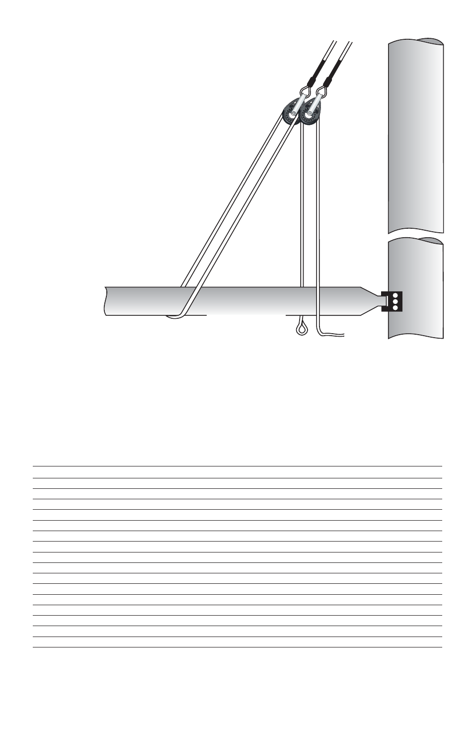
Eye Splice
This will be adjusting side
Determining Location of Boom Hardware
Measure the mainsail foot length or find the E dimension of the mast. Find this mea-
surement in the left column below and circle the corresponding numbers in the right
column. Put a mark on the boom at each measurement. See drawing, page 5.
*Note - You may want to check sail containment before drilling holes in the boom. To
do this, put sail on, tape the boom hardware in place, reeve lines through system and
lower sail. Move if necessary.
8'1" (2.616 m)
2'10" (864 mm)
3.83 - 3.96 m
12'7" to 13'
7'9" (2.362 m)
2'8" (813 mm)
3.68 - 3.82 m
12'1" to 12'6"
7'5" (2.261 m)
2'7" (787 mm)
3.53 - 3.67 m
11'7" to 12'
7'1" (2.159 m)
2'6" (762 mm)
3.37 - 3.52 m
11'1" to 11'6"
6'10" (2.083 m)
2'4" (711 mm)
3.22 - 3.36 m
10'7" to 11'
6'6" (1.981 m)
2'3" (686 mm)
3.07 - 3.21 m
10'1" to 10'6"
6'2" (1.880 m)
2'2" (660 mm)
2.92 - 3.06 m
--9'7" to 10'
5'10" (1.778 m)
2'-------(610 mm)
2.76 - 2.91 m
--9'1" to 9'6"
5'6" (1.676 m)
1'11" (584 mm)
2.61 - 2.75 m
--8'7" to 9'
5'3" (1.600 m)
1'10" (559 mm)
2.46 - 2.60 m
--8'1" to 8'6"
4'11" (1.499 m)
1'9" (533 mm)
2.31 - 2.45 m
--7'7" to 8'
4'7" (1.397 m)
1'7" (483 mm)
2.15 - 2.30 m
--7'1" to 7'6"
4'3" (1.295 m)
1'6" (457 mm)
2.00 - 2.14 m
--6'7" to 7'
4' (1.219 m)
1'5" (432 mm)
1.85 - 1.99 m
6'1" to 6'6"
3'8" (1.118 m)
1'3" (381 mm)
1.70 - 1.84 m
5'7" to 6'
3'4" (1.016 m)
1'2" (356 mm)
1.54 - 1.69 m
5'1" to 5'6"
3' (914 mm)
1'1" (330 mm)
1.39 - 1.52 m
4'7" to 5'
2'8" (813 mm)
11"----(279 mm)
1.24 - 1.38 m
--4'1" to 4'6"
2'5" (737 mm)
10"----(254 mm)
1.09 - 1.23 m
--3'7" to 4'
Chart B – Location of Boom Hardware*
“E” Dimension or
Sail Foot Length
Cheek Block and
Deadend Location
Boom Cradle
Strap Location
Stringing the Control Lines
Decide whether the adjusting block and cleat
will be on port or starboard. The end of the line
without the eye splice will be on the side of
the boom where you will adjust the Lazy Jacks
– the side where you will install the cleat.
With the middle of the control line draped
under the boom, pass the ends of the line
up and run each end of the line through
the blocks that are suspended from the
wire. Run the line through the blocks
from stern to bow as shown in the
diagram below.
4