Guralp Systems CMG-5TD User Manual
Page 18
Operation
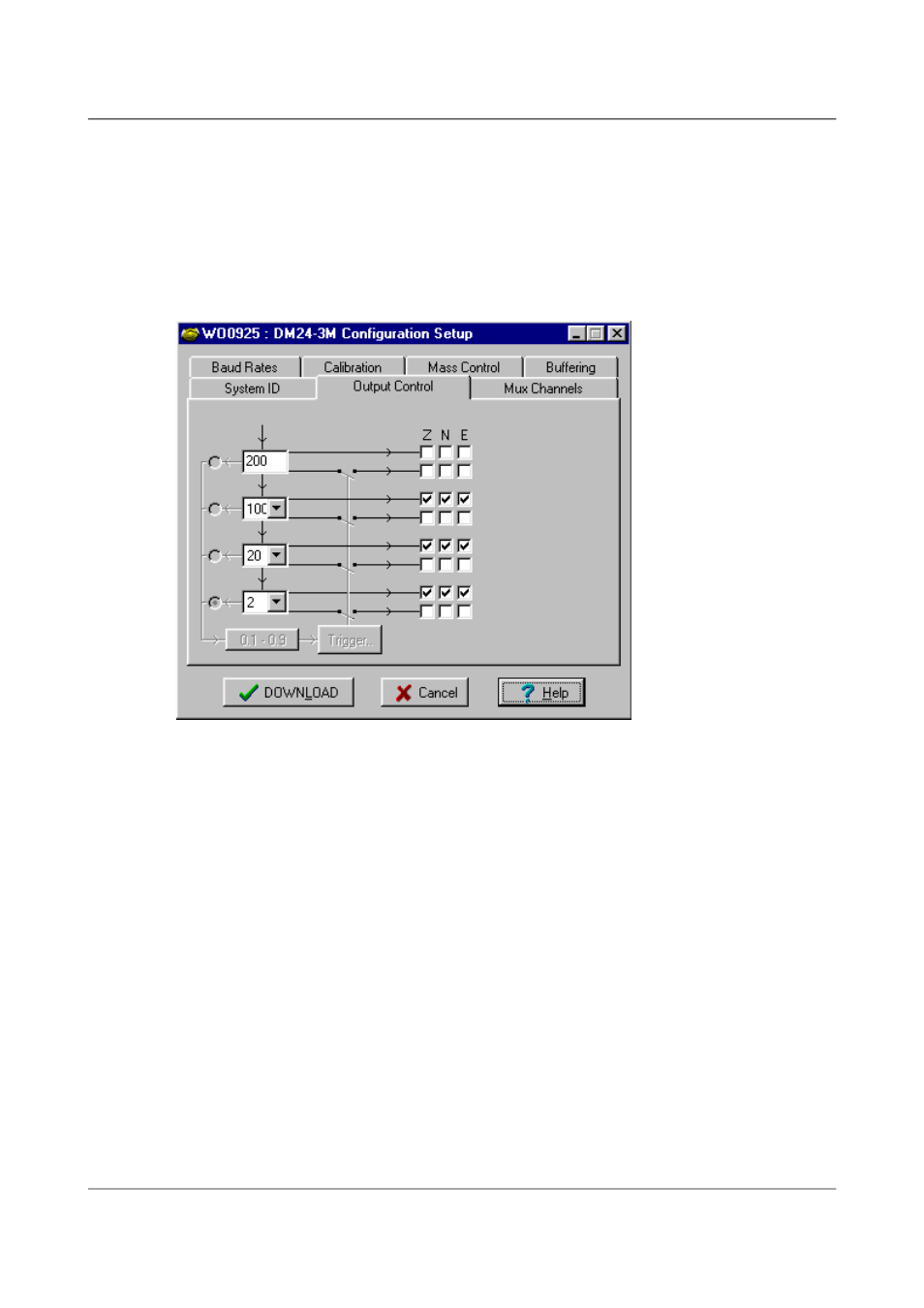
The four text-fields on the left of the Output Control tab allow you to select
the sampling rates for each of the four digitiser taps. Each of the taps must
have a sampling rate lower than the one above but the rate must be achievable
using decimation by a factor of 2, 4, 5, 8 or 10. Each drop-down menu offers a
list of the rates that are permitted, given the sampling rate on the line above it.
If some of the outputs are not required, leave the check-boxes clear in order to
reduce communications bandwidth requirements.
Stream selection: The digitiser has three channels or streams. These are
depicted by the three columns labelled Z, N and E in the Output Control
window shown above.
A tick in a box will give an output for the corresponding channel (column) at
the corresponding sample rate (row). For each sample rate there are two
possible rows to tick. The upper row for each sample rate will give a
continuous output at that sample rate; the lower row, shown
diagrammatically as passing through a switch, will only output data when its
trigger criteria are met (see below).
The Stream IDs displayed in the main Available Streams window have
six-character ID’s. The first four characters identify the digitiser and the last
two characters identify the stream from the digitiser. The first of these two
characters identify the channel, while the second defines the ‘tap’, or digitiser
output ( see Data Transmission Protocol & Data Block Structure later).
For example; for the Output Control configuration shown above, there will be
three data streams, Z, N and E, providing continuous data at 100sps, 20sps
and 2sps. This is shown below, where the digitiser ‘1123’ has the following
streams:-
18
Issue D - April 2013