2 jumper configuration for low gain operation – Guralp Systems CMG-5TD User Manual
Page 11
Setting the gain
Note: The lid-to-body seal uses 'O'-rings. Take care that the
lid does not suddenly fly off when this seal is broken.
•
Lift the lid and the attached electronics vertically out of the cylindrical
body and disconnect the ribbon cable at either end, noting the
orientation of the cable.
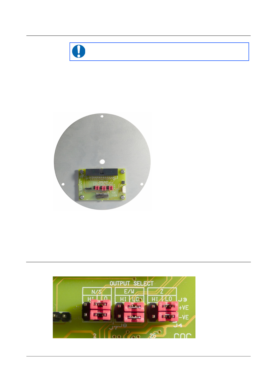
Looking down into the body of the instrument, you will see a small printed
circuit board mounted on an aluminium disc. This board contains the
gain-setting jumpers, which are coloured red to aid identification.
Each component (vertical, North/South and East/West) has two associated
jumpers (one for each leg of the differential connection) and these must
always be moved in pairs. It is possible to select different gains for different
channels but this is rarely desirable. Consult the markings on the printed
circuit board and the pictures below to select the desired gain.
4.2
Jumper configuration for low gain operation
Arrange the jumpers as in the picture below:
11
Issue D - April 2013