Gullco GK-200-RL User Manual
Page 8
6
The drive engagement lever is the 90º lever that extends out of the side of the carriage lower
housing. This lever engages the drive gear with the rack and must always be disengaged when
fitting or removing the "KAT" carriage from the ends of the track. It also permits free wheeling for
rapid positioning. To engage the drive, push lever in towards the carriage body and turn in an anti-
clockwise direction. To disengage drive, push lever in towards the carriage body and turn in a
clockwise direction.
WARNING!
Never disengage the drive, when there is a possibility that this action may result in
the equipment falling to the ground due to load.
The wheel adjustment screw moves the pivoted bogey wheel assembly relative to the track and is
used to facilitate the fitting of the carriage anywhere along the track length. To fit the carriage,
slacken the lock nut (item # 3 – drawing # GK-191-P-200-2B) and turn the adjusting screw (item # 2
– drawing # GK-191-P-200-2B) anti-clockwise to withdraw the wheels to their fullest extent. Fit the
carriage to the track making sure that the fixed wheel assemblies are engaged on the track ways,
then turn the adjusting screw clockwise until all wheels fit snugly on the track ways. The “KAT”
carriage should be free to move along the track, but there should be no play between the wheels
and the track. Tighten up the lock nut. To remove the carriage from the track, perform a reverse
operation to that described above.
NOTE:
Over-tightening of the wheel assemblies will result in overloading the drive system.
NOTE:
If the carriage is being removed or fitted over the end of a length of track, then it is not
necessary to withdraw the wheel bracket assembly.
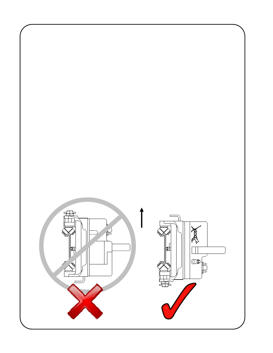
NOTE:
If it is necessary that the carriage is to be mounted to track in the plane shown by the
following sketch, always mount the “KAT” with the fixed wheels on the top, as shown.
UP