Gullco GK-200-RL User Manual
Page 22
20
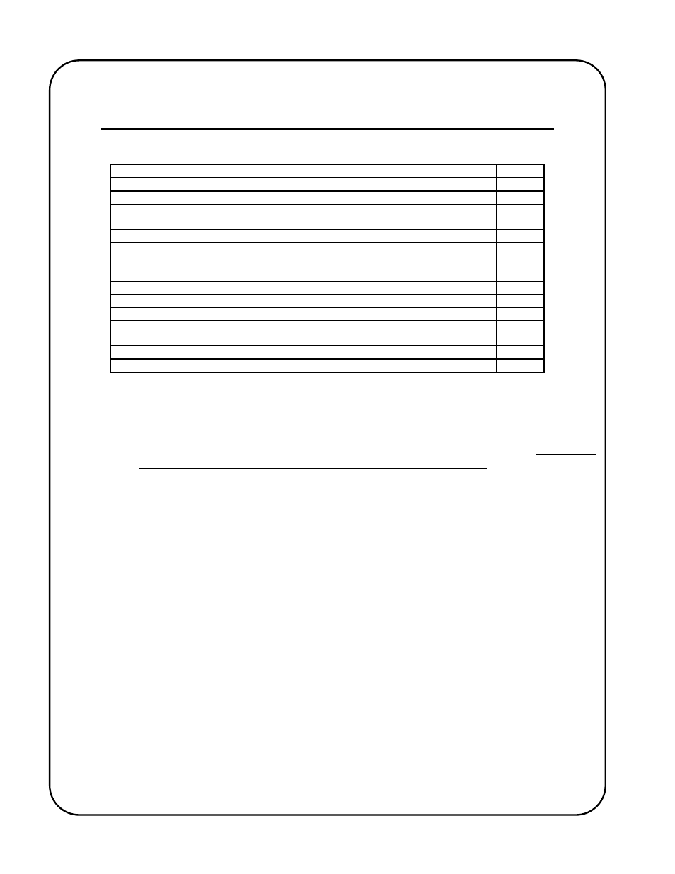
PARTS BREAKDOWN FOR HIGH AND LOW SPEED GEAR ASSEMBLIES
Refer to sketches on previous page.
ITEM PART NUMBER DESCRIPTION
QTY
120
GK-166-169
LOW SPEED GEAR TRAIN ASSEMBLY (ITEMS 121 TO 127)
121
GK-166-171
PINION ON MOTOR SHAFT
1
122
GK-117-008
SPRING PIN, 1/8" x 3/4"
1
123
GK-166-229
IDLER GEAR COMPLETE (ITEMS 124 TO 126)
1
124
GK-166-174
IDLER GEAR
1
125
GK-166-127
IDLER GEAR BEARING
1
126
GK-104-050
SHOULDER SCREW, 1/2" x 1"
1
127
GK-109-052
HEXAGONAL NUTS, 5/16"-18
6
130
GK-166-153
HIGH SPEED GEAR TRAIN ASSEMBLY (ITEMS 131 TO 136)
131
GK-166-130
IDLER GEAR COMPLETE (ITEMS 132 TO 134)
1
132
GK-166-129
IDLER GEAR
1
133
GK-166-127
IDLER GEAR BEARING
1
134
GK-104-050
SHOULDER SCREW, 1/2" x 1"
1
135
GK-166-128
PINION ON MOTOR SHAFT
1
136
GK-117-008
SPRING PIN, 1/8" x 3/4"
1
WARNING!
The attachment of Low Speed or High Speed Gear Assemblies will result in the
reversal of the carriage travel directions. I.e. what was Forward motion will become
Reverse motion and visa versa once the gear assembly is installed. Corrective
measures must be taken if travel limit switches are installed. The easiest way to
restore the correct travel directions is to reverse the motor leads.