Gullco GK-200-RL User Manual
Page 36
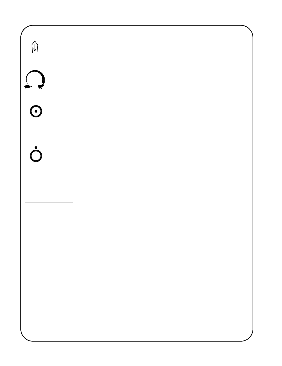
T-6
= “REVERSE” - When the switch is in this position, the control will drive the motor in
the Reverse direction, while in manual mode and when so permitted. It is also used
as the method of adjustment for the program variables when used in conjunction with
the speed adjustment knob.
= “VARIABLE SPEED CONTROL” - By turning the multi turn rotary encoder knob in
a clockwise direction, the motor speed will be increased. When rotated in the
counter-clockwise direction, the motor speed will decrease. The Variable Speed
Control adjustment is normally used to set the manual speed of the motor and the
welding/cutting speed of the motor commanded in an automatic cycle.
= “PRESET CYCLE ENABLED” - Only by depressing the Cycle Push Button
continually for one second while the Fwd/Neut/Rev switch is in the Reverse position,
and while the control is in “Hold” (Stop) mode, may the preset cycle routine be
toggled from disabled to enabled (as indicated by the constant illumination of the
Auto Cycle Mode L.E.D.). The Cycle Push Button is also used to enter and exit
parameter/variables menu.
= “PRESET CYCLE DISABLED” - Only by depressing the Cycle Push Button
continually for one second while the Fwd/Neut/Rev switch is in the Reverse position,
and while the control is in “Hold“ (Stop) mode, may the preset cycle routine be
toggled form enabled to disabled (as indicated by the non-illumination of the Auto
Cycle Mode L.E.D.). The Cycle Push Button is also used to enter and exit
parameter/variables menu.
The L.E.D. Display
The control has an L.E.D. display that indicates the travel speed in one of four possible calibration
scales. The calibration scale selection is made using the Motor Control Variables, Rotary Switch,
described later in this manual. The four possible calibration scales are as follows:
1. Calibration in inches per minute (IPM L.E.D. will be illuminated and the closed loop tach
feedback system is required);
2. Calibration in centimetres per minute (CM/MIN L.E.D. will be illuminated and the closed loop
tach feedback system is required);
3. Calibration in other units such as degrees per minute (no L.E.D. will be illuminated and the
closed loop tach feedback system is required, or;
4. Calibration in percentages of full speed obtainable (0 to 100% pulse width duty cycle) (no
L.E.D. will be illuminated and automatically selected when no closed loop tach feedback is
recognized).
Whenever the control is in Stop (hold) mode and there is no Forward or Reverse direction
commanded (Neutral), the speed display will indicate the preset speed.