High and low speed gear assemblies – Gullco GK-200-RL User Manual
Page 21
19
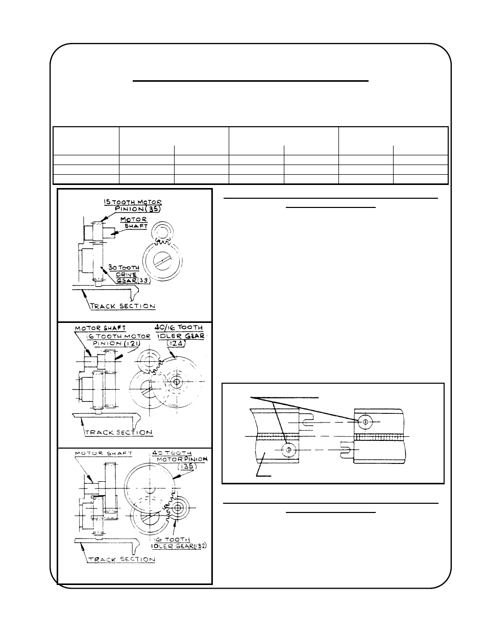
STANDARD GEAR ASSEMBLY
LOW SPEED GEAR ASSEMBLY
HIGH SPEED GEAR ASSEMBLY
HIGH AND LOW SPEED GEAR ASSEMBLIES
Two spur gear trains are available which can easily be fitted to any GK-200-R "KAT" carriage, to
either increase or decrease the speed range of the unit. The following chart gives the speed ranges
obtainable from the various "KAT" carriage models.
STANDARD SPEED
RANGE
WITH LOW SPEED GEAR
ATTACHMENT FITTED
WITH HIGH SPEED GEAR
ATTACHMENT FITTED
MODEL
Inches/Min CM/Min Inches/Min CM/Min Inches/Min CM/Min
GK-200-RL
0.5 – 16.4
1.2 – 41.6
0.2 - 7
0.5 – 17.7
1.3 – 43.6
3.3 - 111
GK-200-RM
1 – 32.7
2.5 – 83.1
0.4 - 14
1 – 35.5
2.6 – 87.3
6.6 – 222
GK-200-RH
2.7 – 88.4
6.7 - 224
1.1 – 37.7
2.9 – 95.8
7.1 - 236
18 – 598
INSTALLATION INSTRUCTIONS FOR LOW SPEED GEAR
ASSEMBLY GK-166-169
1. Remove
top
housing.
2. Remove motor mounting screw.
3. Drive out spring pin from motor shaft and remove motor
pinion.
4. Mount idler gear on motor fork bracket using shoulder
screw.
5. Mount 16-tooth gear on motor shaft, align to mesh with gear
and fit drive pin.
6. Refit motor into lower housing and replace top cover.
NOTE: When the low speed gear assembly is fitted, the
following track changes are IMPORTANT. The
standard track is equipped with 1" diameter knurled
nuts on the locking assembly. These nuts must be
changed to 5/16 hex full nuts to provide the necessary
gear clearance. Six of the 5/16-18 nuts - Part No. GK-
109-052, are supplied with every low speed gear train -
see illustration below.
INSTALLATION INSTRUCTIONS FOR HIGH SPEED GEAR
ASSEMBLY GK-166-153
1. Remove
top
housing.
2. Remove Motor Mounting Screw.
3. Drive out spring from motor shaft and remove motor pinion .
4. Install idler gear using shoulder screw.
5. Mount 40-tooth gear on motor shaft and fit drive pin.
6. Refit motor into lower housing and replace top cover.
Replace 1” dia. Knurled nuts
with 5/16”-18 hex nuts
Standard rigid track