Gullco GK-200-RL User Manual
Page 41
T-11
If the specific product/application for which a control is to be used and unless otherwise specified,
the Motor Control Variables will be factory pre-set as follows:
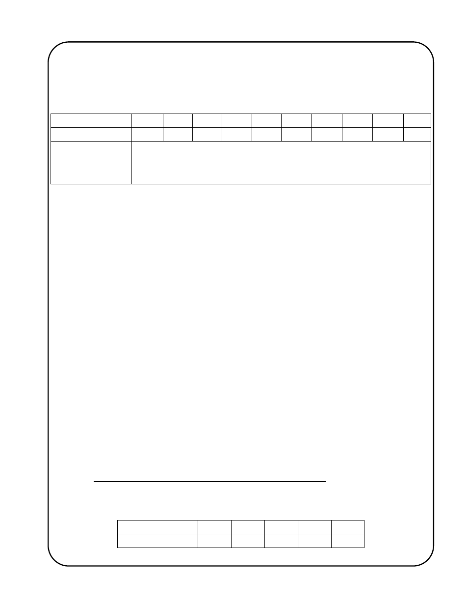
Variable/Parameter
A. 1
A. 2
A. 3
A. 4
A. 5
A. 6
A. 7
A. 8
A. 9
A.10
Value/Setting 10.0 10 00 00
_
_
_
Inc 001 002 100 -1
Overall Result
The control will allow a current draw of up to 10 amperes. The speed will be
calibrated so that full speed will display 100 IPM. The braking will be close to
instantaneous. The speed correction response will be medium. 100% of full
speed will be available.
The Gullco “GSP-2100” motor controller needs to have the speed display calibrated to match that of
the equipment driven by the motor. This is required so that the speed displayed is equal to that of
the motion and also so that the control may calculate engineering units (counting and scaling of
tach feedback pulses, used to measure distance travelled). If the product/application specific
program utilises engineering units, the calibration of the speed is very important. For this reason,
the speed calibration is performed with an accuracy of six digits, even though the speed displayed
is only three digits. After the calibration process has been completed, the three least significant
digits are not displayed.
As mentioned earlier, the accuracy of the calculated engineering unit output is only as good as the
calibration of the control relevant to the actual speed. The following example shows how to
calculate the actual full speed of a Gullco “KAT
®
” carriage.
Known Factors:
Control is running at full speed when receiving 2KHz from tach feedback sensor.
Sensor wheel on motor armature creates 20 pulses per revolution.
Gear box ratio = 540:1
External gear drive = 15 tooth to a 30 tooth, gear ratio.
Pitch diameter of the 30 tooth final drive gear = 1.875”
Calculation:
2KHz. = 120,000 pulses per minute.
120,000 pulses per minute / 20 pulses per rev = 6000 revs per minute (armature)
6000 rpm (armature) / 540 (gearbox ratio) = 11.111111 rpm (output shaft of gear box)
11.111111 rpm x 15/30 (external gear ratio) = 5.555556 rpm (final drive gear)
1.875” (pitch diameter) x Pi = 5.890486” (circumference)
5.555556 rpm x 5.890486” per rev = 32.7249” per minute
Therefore maximum travel speed = 32.7249 inches per minute
In the above example, the speed calibration values of the Motor Control Variables would be set as
follows:
Variable/Parameter
A. 2
A. 3
A. 4
A. 5
A. 6
Value/Setting 32 72 49
_
_
. _
Inc