Duct connections to the bypass air plenum (bap), Plenum drainage piping / trap detail (by others) – Greenheck Vektor-MH, Vektor-MD, and Vektor-MS (464652) User Manual
Page 9
Duct Connections to the Bypass Air
Plenum (BAP)
Connecting primary inlet exhaust air ducts is allowed
through the roof curb or through one or more of the
side access panels. To reduce the potential for system
effects in the plenum, the duct connection should be
sized to have no more than a maximum air velocity of
1500 fpm when entering. When attaching ductwork
to the plenum, care should be taken to ensure a
tight fit and proper seal to prevent leakage from the
contaminated airstream.
Side Inlet Duct Connections
Ductwork that has a different size than the removable
access panel(s) can either have a transition to the
plenum’s opening size or the access panel can be
field modified by cutting an opening to the size of the
ductwork.
Bottom Inlet Duct Connections
Bottom inlet duct connects should be made by
attaching the duct to the inside panel edge of the
plenum. Ducting to multiple fan plenums may either
be split below the roof level and connected to duct
drops from the inside the plenum or having the ducting
notched for fitting around roof curb and plenum cross
support members.
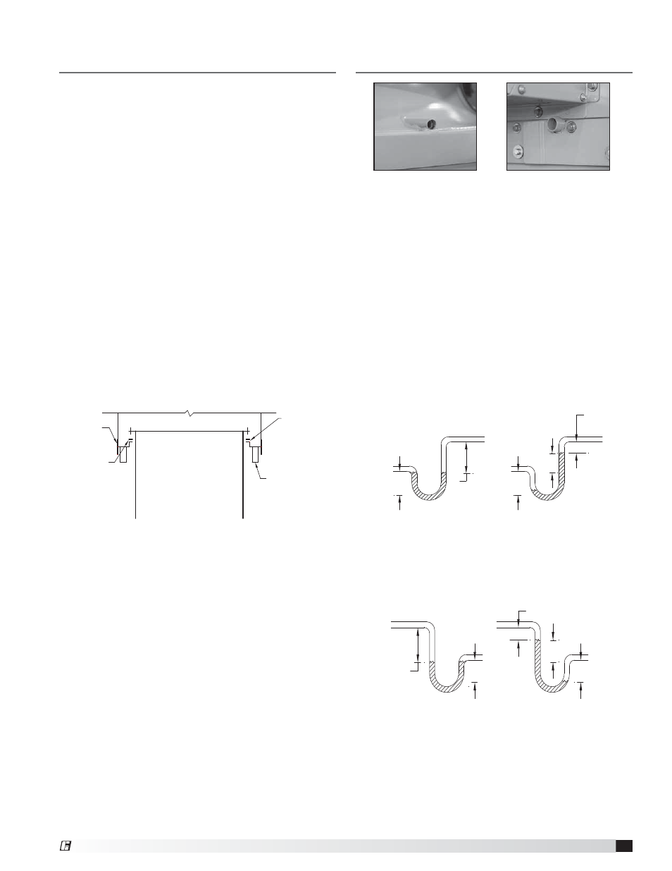
Plenum Drainage Piping / Trap
Detail (By Others)
There is a location for a pipe connection on each tubular
fan housing and bypass air plenum. Each drain may
need to be connected to a drainage system to ensure
proper disposal of any water or condensate that may
occur.
• Drain connections are 0.5 inch FNPT and
1.0 inch MNPT
•
Installed piping to have a downward angle to allow
for drainage
•
Fill traps to recommended level before start-up
Note: A conservative method of trap design is to set N
= total static pressure.
Check local codes for proper disposal of drain water
which has been in contact with the exhaust air.
Positive Pressure Trap on Tubular Fan
Housing
Fan Drain
Connection
Plenum Drain
Connection
Negative Pressure Trap on Bypass Air
Plenum
N = Negative fan pressure (inches W.C.)
H = N - 0.5 inches minimum
H/2
H/2
H
1.25 inch minimum
N
FAN ON
FAN OFF
N = Negative fan pressure (inches W.C.)
H = N - 0.5 inches minimum)
H/2
H/2
H
1.25 inch
minimum
N
FAN ON
FAN OFF
Connect
this end
to fan drain.
Duct connections are to be sealed from air leakage and
water penetration.
Flanged
Bottom Inlet
Gasket/Seal
(by others)
Bolt-On
Mounting
Skirt
Roof Curb or
Structure
Duct Drop
(by others)
Plenum bottom section view for single fan system.
Repeated for multiple fan plenums.
9
Laboratory Exhaust Systems
®