Electrical connections, Single phase layout, Three phase layout – Greenheck Vektor-MH, Vektor-MD, and Vektor-MS (464652) User Manual
Page 11: Laboratory exhaust systems
Before electrical connections are made, the supply
voltage, phase and ampere capacity must be checked
for compatibility with the fan motor. In addition, the
supply wiring must be properly fused and conform to
local and national electrical codes. If the unit is supplied
with a safety disconnect switch, ensure proper wiring
to the fan motor. Be sure the disconnect is switched to
the “OFF” position before connecting supply wires. If
no disconnect is supplied, ensure the supply wire is not
live before connection. Supply wires are then connected
to the optional safety disconnect switch (if supplied) or
motor.
Vektor-MH and Vektor-MD Motor Disconnect
and Isolation Damper Wiring Diagram
Disconnect is mounted to fan housing. Transformers are
mounted to bypass air plenum with damper actuator
motors. For systems that ship unassembled because
of physical size, this connection at disconnect from
transformers must be field-installed. Wires with conduit
and fittings are provided pre-connected to transformers.
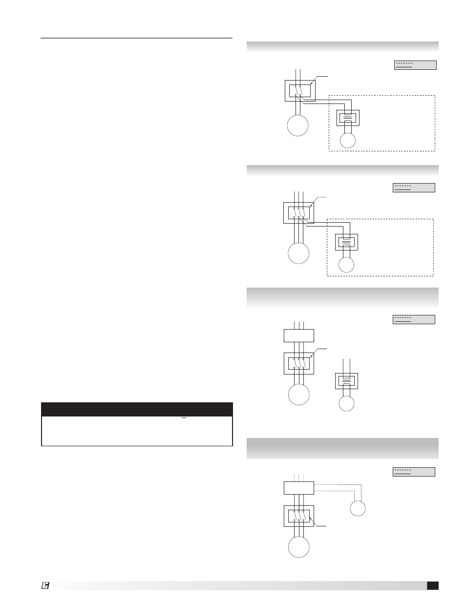
Electrical Connections
Single Phase Layout
LINE IN
115/208/230/277 volt, single phase
MOTOR
DISCONNECT
115/208/230/277 volt
Single phase
TRANSFORMER
208/230/277 volt, single phase
Transformers must be wired independent
from VFD control.
24/115 volt, single phase
isolation damper actuator motor
power open/spring close
115/208/230/277 volt
Single phase
Disconnect is mounted to fan housing
Optional transformer and isolation damper, refer to CAPS file selection
Field Wiring
Factory Wiring
Three Phase Layout
LINE IN
208/230/460/575 volt, three phase
MOTOR
DISCONNECT
208/230/460/575 volt
Three phase
TRANSFORMER
208/230/460/575 volt, single phase
Transformers must be wired independent
from VFD control.
24/115 volt, single phase
isolation damper actuator motor
power open/spring close
208/230/460/575 volt
60 cycle, three phase
Disconnect is mounted to fan housing
Optional transformer and isolation damper, refer to CAPS file selection
Field Wiring
Factory Wiring
Three Phase with
Variable Frequency Drives Layout
Three Phase Motor Starter
with Integral Damper Control Layout
LINE IN
208/230/460/575 volt, three phase
MOTOR
DISCONNECT
208/230/460/575 volt
Three phase
VFD
supplied and wired
by others
TRANSFORMER (if required)
208/230/460/575 volt, single phase
Transformers must be wired independent
from VFD control.
24/115 volt, single phase
isolation damper actuator motor
power open/spring close
208/230/460/575 volt
60 cycle, three phase
Disconnect is mounted to fan housing
Optional transformer and isolation damper,
refer to CAPS file selection
Field Wiring
Factory Wiring
LINE IN
208/230/460/575 volt, three phase
MOTOR
DISCONNECT
208/230/460/575 volt
Three phase
Motor Starter
with Intergral
Damper Control
24/115 volt, single phase
isolation damper actuator motor
power open/spring close
208/230/460/575 volt
60 cycle, three phase
Disconnect is mounted
to fan housing
Optional isolation damper,
refer to CAPS file selection
Field Wiring
Factory Wiring
Vektor-MH and Vektor-MD Applications with
Variable Frequency Drives (VFD)
For Vektor systems with single-point, three-phase
wiring per blower, the isolation damper actuator will be
powered via a step-down transformer, which is wired
to the fan disconnect, as shown in the appropriate
diagram.
If fan flow (motor speed) is to be controlled using a
variable frequency drive with this wiring, the reduced
voltage and frequency supplied to the fan will cause
control problems with the isolation damper actuator.
When a project’s Vektor control sequence requires the
use of a VFD, it is suggested that the control contractor
supply the isolation damper actuator voltage —
independent of the power supplied to the Vektor fan
motor.
NOTE
For Vektor-MS fans refer to the Vektor SAVVE controls
Installation, Operation and Maintenance Manual for
electrical wiring and connection information.
11
Laboratory Exhaust Systems
®