Greenheck ERV (476412) User Manual
Page 23
23
Energy Recovery Ventilator
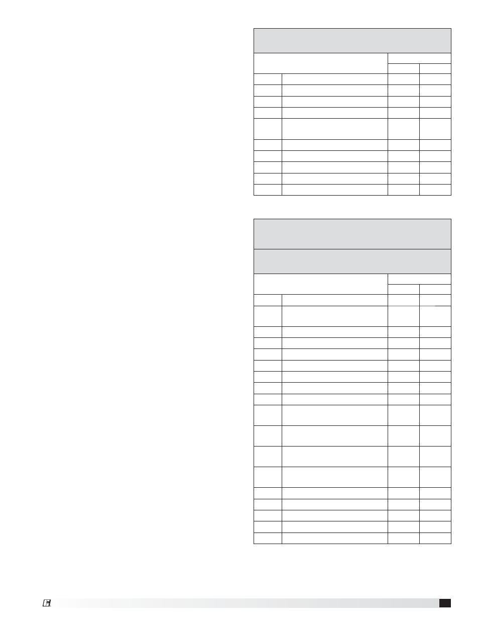
MODULATING CONTROL FOR FAN SPEED
(0-10 VDC)
Parameter
Setting
V1000
J1000
A1-01
Access Level
2
2
B1-17
VFD Start-Up Setting
1
1
C6-02
Carrier Frequency
1
1
D2-02
Ref Lower Limit
50%
50%
E2-01
Motor Rated FLA
Motor
FLA
Motor
FLA
H2-01
Terminal MA, MC Function
5
5
H3-04
Terminal A1 Bias
50%
50%
L4-01 H2-01 Frequency Detection
15
15
L5-01
Auto Restart Attempt
5
5
A1-01
Access Level
0
0
CO
2
SENSOR CONTROL FOR FAN SPEED
(1/2 SPEED WHEN CO
2
DROPS BELOW 700 PPM)
(FULL SPEED WHEN CO
2
RISES ABOVE 800 PPM)
MULTI-SPEED CONTROL FOR FAN SPEED
(1/3 OR 1/2 SPEED REDUCTION)
Parameter
Setting
V1000
J1000
A1-01
Access Level
2
2
B1-01
Reference Source
(Frequency)
0
0
B1-17
VFD Start-Up Setting
1
1
C6-02
Carrier Frequency
1
1
D1-01
Frequency Reference 1
60 Hz
60 Hz
D1-02
Frequency Reference 2
40 Hz
40 Hz
D1-03
Frequency Reference 3
30 Hz
30 Hz
D1-04
Frequency Reference 4
60 Hz
60 Hz
D2-02
Ref Lower Limit
50%
50%
E2-01
Motor Rated FLA
Motor
FLA
Motor
FLA
H1-04
Multi-Function Input Sel 4
(Terminal S4)
3
3
H1-05
Multi-Function Input Sel 5
(Terminal S5)
4
4
H1-06
Multi-Function Input Sel 6
(Terminal S6)
5
NA
H2-01
Terminal MA, MC Function
5
5
H3-10
A2 Not Used
F
NA
L4-01 H2-01 Frequency Detection
15
15
L5-01
Auto Restart Attempt
5
5
A1-01
Access Level
0
0
Factory Set Points
Variable frequency drives (VFDs) for the blowers are
factory setup to operate in one of the three following
modes:
• Modulating: 0-10 VDC signal wired in the field by
others varies the speed of the blower between 30
and 60 Hz
• Multi-speed: Digital contact closures by others
command the VFD to run at multiple speed
settings:
ż Open - Drive runs at 60 Hz
ż SC to S4 - Drive runs at 40 Hz
ż SC to S5 - Drive runs at 30 Hz
• CO
2
Sensor:
ż Set Point Control: A carbon dioxide sensor is
provided from the factory for field mounting OR
unit mounting in the space(s) being served by
the energy recovery unit. The CO
2
sensors are
wired to the unit VFD’s with two preset speeds
of 700 PPM or less CO
2
= 50% fan speed and
800 PPM or greater CO
2
= 100% fan speed.
ż Proportional Control: A carbon dioxide sensor
is provided from the factory for field mounting
OR unit mounting in the space(s) being served
by the energy recovery unit. The CO
2
sensors
are wired to the unit VFD’s with default factory
settings of 500 PPM or less CO
2
= 50% fan
speed and 1000 PPM or greater CO
2
= 100% fan
speed. Modulation of VFD occurs proportional
to CO
2
between 500 and 1000 PPM.
The terminal locations for modulating and multi-
speed are shown on the previous page. Most of the
set points in the VFDs are Yaskawa factory defaults.
However, a few set points are changed at Greenheck
and are shown in the tables. These settings are
based on the VFD mode selected.
Change Set Points
To gain access to change set points on the V1000 and
J1000 drives, parameter A1-01 needs to be set at “2”.
To prevent access or tampering with drive settings on
either drive, change parameter A1-01 to “0”.
• Drive
Operation
ż SC to S1 contact for On/Off
ż A1 (0-10 VDC) referenced to AC.
Can use +15 VDC from +V.
Resetting the V1000 drive to factory defaults
To reset the V1000 drive back to Greenheck factory
defaults, go to parameter A1-01 and set it to “2”.
Then go to A1-03 and change it to “1110” and press
enter. The drive is now reset back to the settings
programmed at Greenheck. This option is not
available on the J1000.