Optional start-up components, Air seals, Drive belt – Greenheck ERV (476412) User Manual
Page 20: Vibration, Energy recovery wheel, Dirty filter switch
20
Energy Recovery Ventilator
Air Seals
Check that the air seals located around the outside of
the wheel and across the center (both sides of wheel)
are secure and in good condition. Air seal clearance
is determined by placing a sheet of paper, to act as a
feeler gauge, against the wheel face. To access seals,
enter the unit for the ERV-55 and 120, or pull out the
cassette for the ERV-10, 20, 45, and 90, following
the instructions in the Energy Recovery Wheel
Maintenance section. To adjust the air seals, loosen
all eight seal retaining screws. These screws are
located on the bearing support that spans the length
of the cassette through the wheel center. Tighten the
screws so the air seals tug slightly on the sheet of
paper.
Replace cassette into unit, plug in wheel drive,
replace access door and apply power. Observe by
opening door slightly (remove filters if necessary to
view wheel) the wheel should rotate freely at about
50-60 RPM.
Drive Belt
Inspect the drive belt. Make sure the belt rides
smoothly through the pulley and over the wheel rim.
Vibration
Excessive vibration may be experienced during initial
start-up. Left unchecked, excessive vibration can
cause a multitude of problems, including structural
and/or component failure. The most common sources
of vibration are listed.
Many of these
conditions can be
discovered by careful
observation. Refer to
the Troubleshooting
section of this manual
for corrective actions.
If observation cannot
locate the source of
vibration, a qualified
technician using vibration analysis equipment should
be consulted. If the problem is wheel unbalance,
in-place balancing can be done.
Generally, fan vibration and noise is transmitted
to other parts of the building by the ductwork. To
eliminate this undesirable effect, the use of heavy
canvas connectors is recommended.
Wheel Unbalance
Drive Pulley Misalignment
Incorrect Belt Tension
Bearing Misalignment
Mechanical Looseness
Faulty Belts
Drive Component Unbalance
Poor Inlet/Outlet Conditions
Foundation Stiffness
Energy Recovery Wheel
The ERV models contain a total energy recovery
wheel. The wheels are inspected for proper
mechanical operation at the factory. However, during
shipping and handling, shifting can occur that may
affect wheel operation. The wheel is accessible
through the access door marked “Energy Wheel
Cassette Access”. For the ERV-10, 20, 45, and 90,
the wheel cassette(s) slide out. Due to the size and
weight of the ERV-55 and 120 wheels, they remain
stationary and all maintenance is performed in place.
There is room inside the unit to perform energy
recovery wheel servicing.
Turn the energy recovery wheels by hand to verify
free operation. The wheel should rotate smoothly and
should not wobble.
Drive Belt
Adjustable
Air Seals
Label
showing
cassette
serial #
and date
code
Bearing
Support
Drive Pulley
Optional Start-Up Components
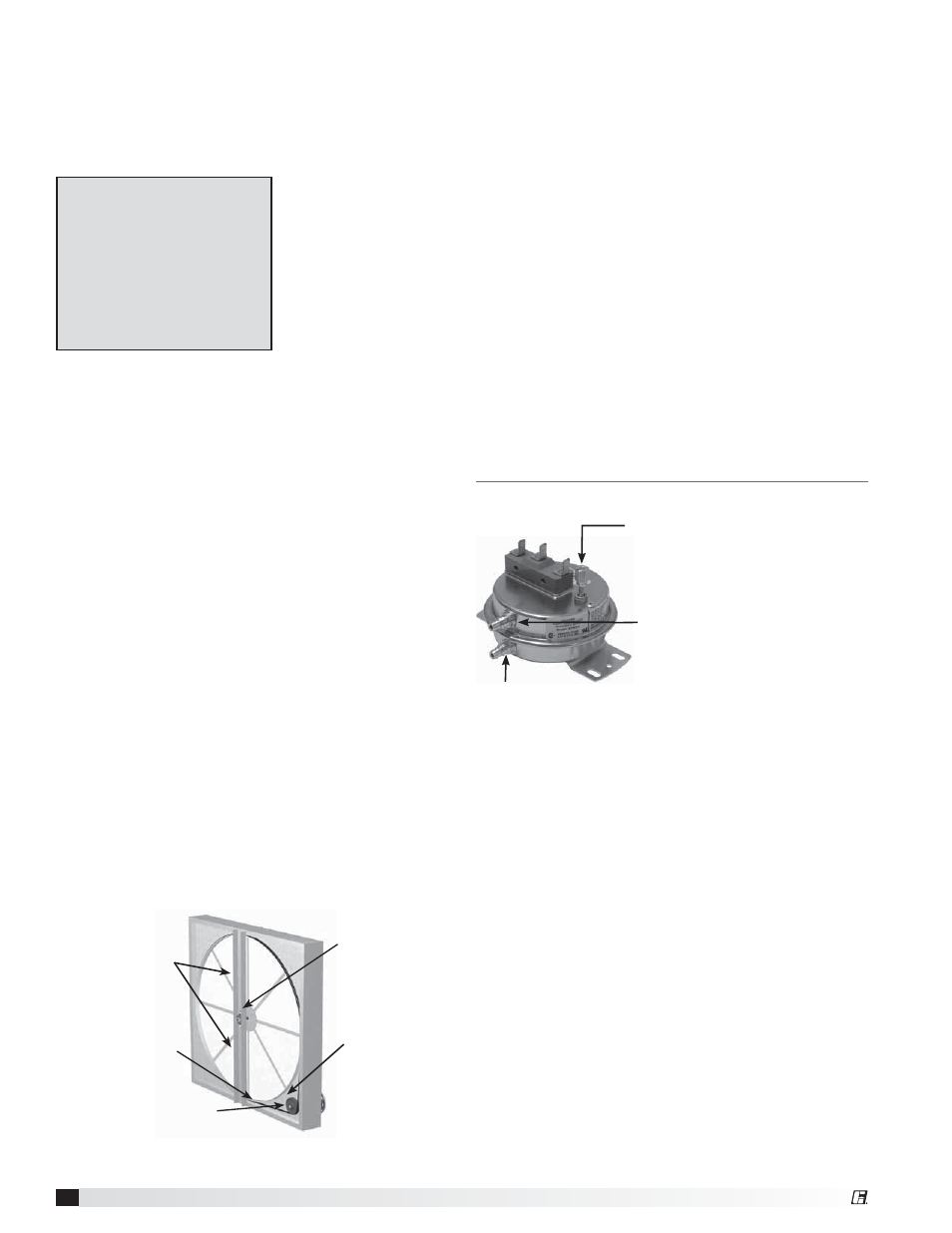
Dirty Filter Switch
To adjust the switch, the unit must be running with
all of the access doors in place, except for the
compartment where the switch is located (exhaust
intake compartment). The adjusting screw is located
on the top of the switch.
1. Open the filter compartment and place a sheet of
plastic or cardboard over 50% of the filter media.
2. Replace the filter compartment door.
3. Check to see if there is power at the alert signal
leads (refer to electrical diagram).
4. Whether there is power or not, turn the
adjustment screw on the dirty filter gauge
(clockwise if you did not have power, counter-
clockwise if you did have power) until the power
comes on or just before the power goes off.
5. Open the filter compartment and remove the
obstructing material.
6. Replace the door and check to make sure that
you do not have power at the alert signal leads.
The unit is now ready for operation.
Setscrew (on front of switch) must
be manually adjusted after the
system is in operation.
Negative pressure connection
is toward the ‘front or top’ of
the switch. (Senses pressure on
the blower side of filters)
Positive pressure connection is toward the ‘back or bottom’
of the switch. (Senses pressure at air inlet side of filters)