Rail mounting / layout, Outdoor air weatherhood, Exhaust weatherhood – Greenheck ERV (476412) User Manual
Page 11: Dampers
11
Energy Recovery Ventilator
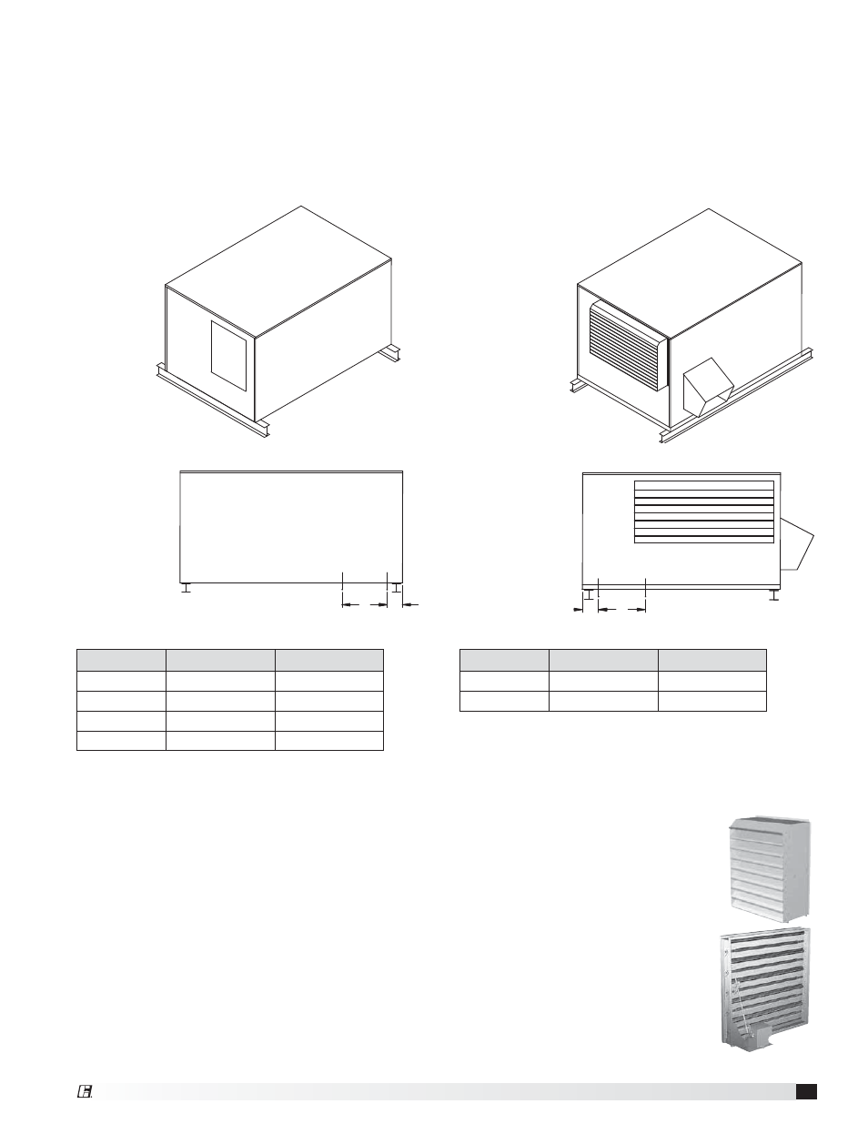
Isometric view of
ERV on rails
Side view of
ERV on rails
OUTDOOR AIR INT
AKE END
OUTDOOR AIR INTAKE END
OUTDOOR AIR INTAKE HOOD
B
SUPPLY/EXHAUST
OPENING
A
ERV-90
ERV-120
Unit Size
A
B
ERV-90
4.625
32
ERV-120
4.875
33.25
All dimensions are in inches.
OUTDOOR AIR SIDE
Isometric view of
ERV on rails
Side view of
ERV on rails
A
B
SUPPLY/EXHAUST
OPENING
OUTDOOR AIR SIDE
ERV-10
ERV-20
ERV-45
ERV-55
Unit Size
A
B
ERV-10
4.50
16
ERV-20
4.75
18
ERV-45
5.75
24
ERV-55
4.875
22
All dimensions are in inches.
Rail Mounting / Layout
• Rails designed to handle the weight of the ERV should be positioned as shown on the diagram (rails by
others).
• Make sure that rail positioning does not interfere with the supply air discharge opening or the exhaust air
intake opening on the ERV unit. Avoid area dimensioned “B” below.
• Rails should extend beyond the unit a minimum of 12 inches on each side.
• Set unit on rails.
Outdoor Air Weatherhood
Outdoor air weatherhood will be factory
mounted.
Exhaust Weatherhood
The exhaust weatherhood is shipped
separately as a kit with its own
instructions.
Dampers
Backdraft dampers are always
included as an integral part of the
exhaust hood assemblies. Motorized
outdoor air and exhaust air dampers
are optional and are factory mounted
(and wired) at the intake.