Appendix, Troubleshooting – Dynacord DMM 4650 User Manual
Page 47
APPENDIX
Troubleshooting
In stand-by mode the DMM 4650 runs a number of test routines in order to detect device faults at an early
stage. Errors are indicated by the flashing of the green POWER LED. With fatal errors or when errors
start to appear more often the blinking of the LED gets faster and the fault relay drops. At the same time,
the audio input is connected directly to the output via the bypass relay.
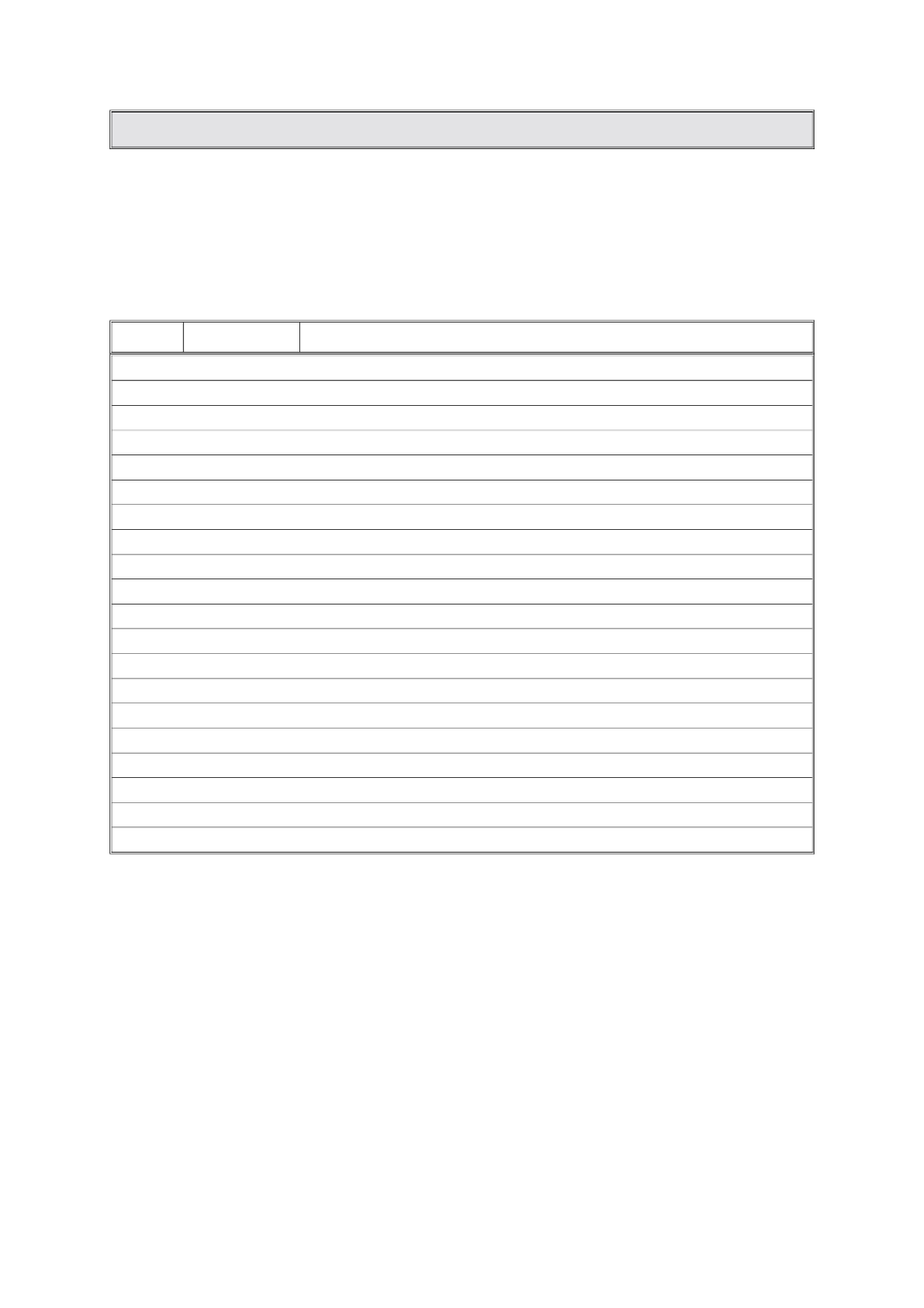
The menu “self test” provides a listing of error numbers and occurence of the following messages:
No:
Error Name
Function test
1
Reset
Power-On counter, no message displayed
2
Software
faulty micro processor interrupt
3
Modul-ID
changing number and activity of control ports (A-D) during power-on
4
+/- 15V
tests internal supply-voltage ± 15V
5
Bypass
function of audio bypass relay (hardware and software)
6
Fault
function of fault relay (hardware and software)
7
User-mem
data error of passwords and their priorities
8
Trig-mem
data error in trigger settings
9
Sequ-mem
data error in user presets of sequences
10
Stop-mem
data error in user settings of stop triggers
11
Alrm-mem
data error in alarm user presets
12
Gong-mem
data error in gong user presets
13
Msg-dir
data error in message file management
14
Msg-chsu
data error in message audio data (see also “message” on page 14 “*”)
15
ARS-RAM
communication error in DSP processor
16
ARS-mod
software error in DSP processor
17
Flash
tests for a changed number of flash memory cards
18
Block
faulty blocks in flash memory has been occurred later
19
EEPROM
error at writing into EEPROM
20
ROM
data modification of the microprocessor’s EPROM
47