Connections, Control inputs and control outputs ports a - d, Control levels and currents – Dynacord DMM 4650 User Manual
Page 30
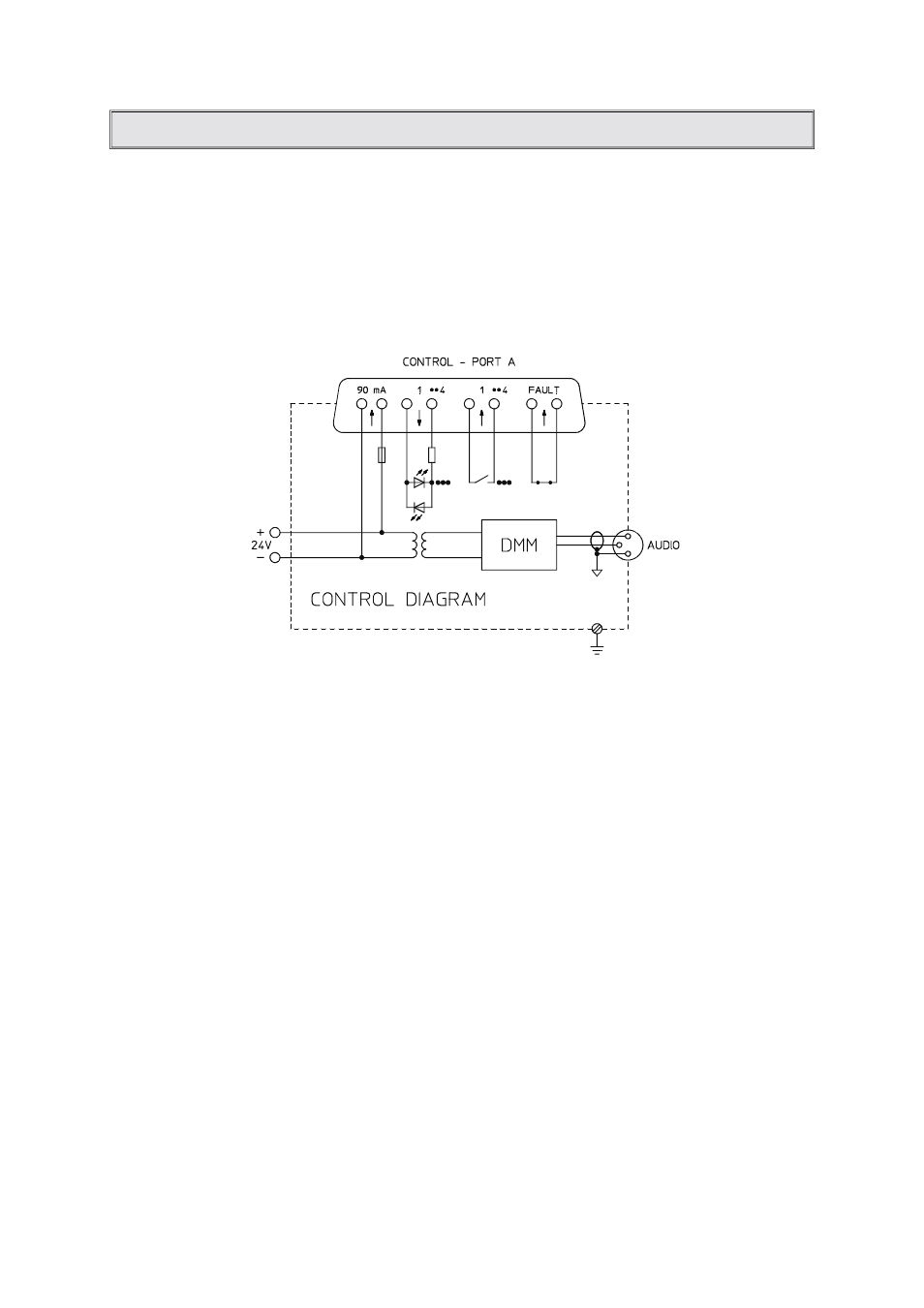
CONNECTIONS
CONTROL INPUTS AND CONTROL OUTPUTS PORTS A - D
General:
Operation see page 21
(PORTS C, D are optional)
Each of the 4 ports (A, B, C, D) have 4 inputs and 4 outputs and a power source for supplying floating
control keys or contacts.
The inputs and outputs are galvanic insulated from the DMM 4650 and the adjacent control lines.
Port A has an additional fault output (relay contact) which, during normal operation, is always closed.
The DMM 4650 provides port connection through 25-pole sub-D connectors (male).
Pin assignment for ports A, B, C, D:
@ corresponds to A, B, C, D
pin
name
pin
name
1
- Batt.
7-20
OUT @1
14
- Batt.
8-21
OUT @2
2-15
INP @1
9-22
OUT @3
3-16
INP @2
10-23
OUT @4
4-17
INP @3
11
- Batt.
5-18
INP @4
24
- Batt.
6
- Batt.
12-25
Fault Out !!Only PORT A
19
- Batt.
13
+ Batt. (max. 90 mA)
Control levels and currents:
Power source -Batt. / +Batt. corresponds to a supply voltage of (20V - 31V) of the DMM 4650. For current
limitation (fuse), a PTC resistor (positive temperature coefficient resistor) is provided at the +Batt
connection of each port.
Inputs:
The polarity of the control inputs is random.
L = low corresponds to
U
INP
< ± 5V (0-5V)
I
INP
< 1mA (0-1mA)
H = high corresponds to
U
INP
> ± 10V (10-31V)
I
INP
> 1.8mA (1.8-7mA)
max. U
inp
= ±31V
30