Assembly instructions – GAMMA 5800 Els STRINGING MACHINE 2 POINT SC MOUNTING (Issue 6 - July 2014) User Manual
Page 6
6
ASSEMBLY INSTRUCTIONS
Floor Stand Height Adjustment
The height of the machine is adjustable from
39” to 46” in approximate 1” increments. To
change the height, remove the socket head
cap screw from its current position and place
it in the appropriate hole to set the desired
height of the machine. Be sure to thread the
screw completely into the Upper Column so
the head of the cap screw rests in the notch
of the Lower Column.
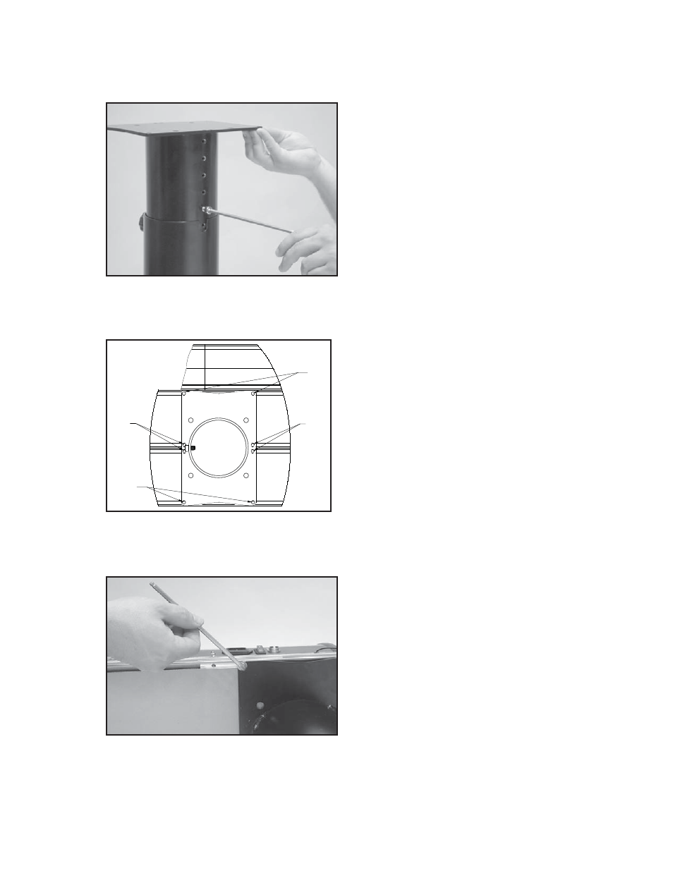
Floor Stand Upper Column Installa-
tion (cont.)
Secure the f ange to the Base of the machine
with the six M6 cap screws packed with the
f oor stand.
Caution:
When securing the screws to
the slide brackets cross threading or over
tightening may damage the threads in the
slide bracket or cause the threads to strip out.
Floor Stand Upper Column Installation
With the height adjustment cap screw on the
Upper Column facing the brake lever & string
length meter, align the six holes marked “X”
in the Upper Column f ange with the threaded
holes in the slide brackets of the Machine Base.
Note: If upper column fl ange is different
from the one pictured, follow the instruc-
tions that were included with the fl oor
stand.
"X"
"X"
"X"
"X"
- 8800 Els STRINGING MACHINE 2 POINT SC MOUNTING (Issue 6 - July 2014) 8800 Els STRINGING MACHINE 6 POINT SC MOUNTING (Issue 9 - July 2014) 5800 Els STRINGING MACHINE 2 POINT SC MOUNTING (Issue 5B - March 2014) 5800 Els STRINGING MACHINE 6 POINT SC MOUNTING (Issue 5B - March 2014) 5800 Els STRINGING MACHINE 6 POINT SC MOUNTING (Issue 7 - June 2014) 5800 Els STRINGING MACHINE 6 POINT SC MOUNTING (Issue 6 - June 2014) 8800 Els STRINGING MACHINE 2 POINT SC MOUNTING (Issue 5B - March 2014) 5800 Els STRINGING MACHINE 6 POINT SC MOUNTING (Issue 6B - March 2014) 8800 Els STRINGING MACHINE 6 POINT SC MOUNTING (Issue 8B - March 2014)